http://www.ta-formation.com/cours/n-fm.pdf
http://www.ta-formation.com/acrobat-modules/fm.pdf
RADIO F.M., Hyperfréquences:
![]() maq-FM.pdf (PDF- 19 pages - 406Kb) Récepteur
en modulation de fréquence
maq-FM.pdf (PDF- 19 pages - 406Kb) Récepteur
en modulation de fréquence
http://www.ta-formation.com/cours/n-fm.pdf
http://www.ta-formation.com/acrobat-modules/fm.pdf
![]()
https://milena-spb.com/collections/kits-et-composants-1/products/kit-radio-fm-76mhz-108mhz-tres-sensible-nouveau-ci-hex-5653
Kit Radio FM 76MHz-108MHz très sensible Nouveau CI HEX 3653
![]()
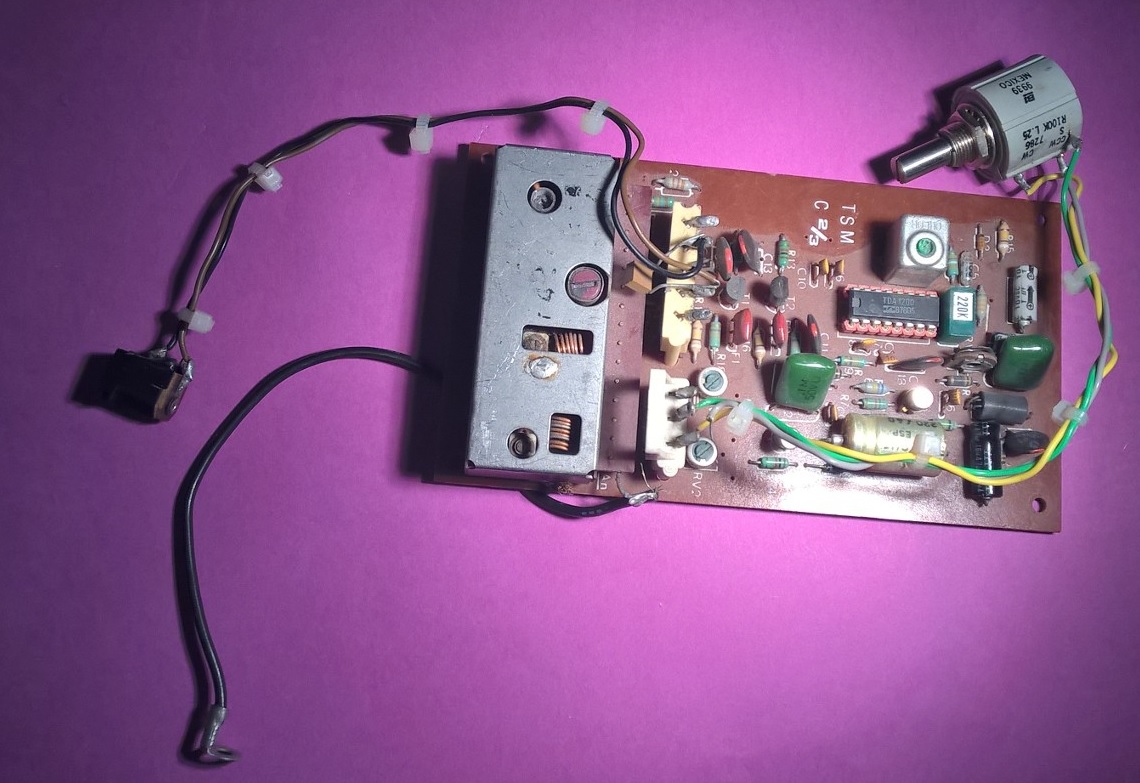
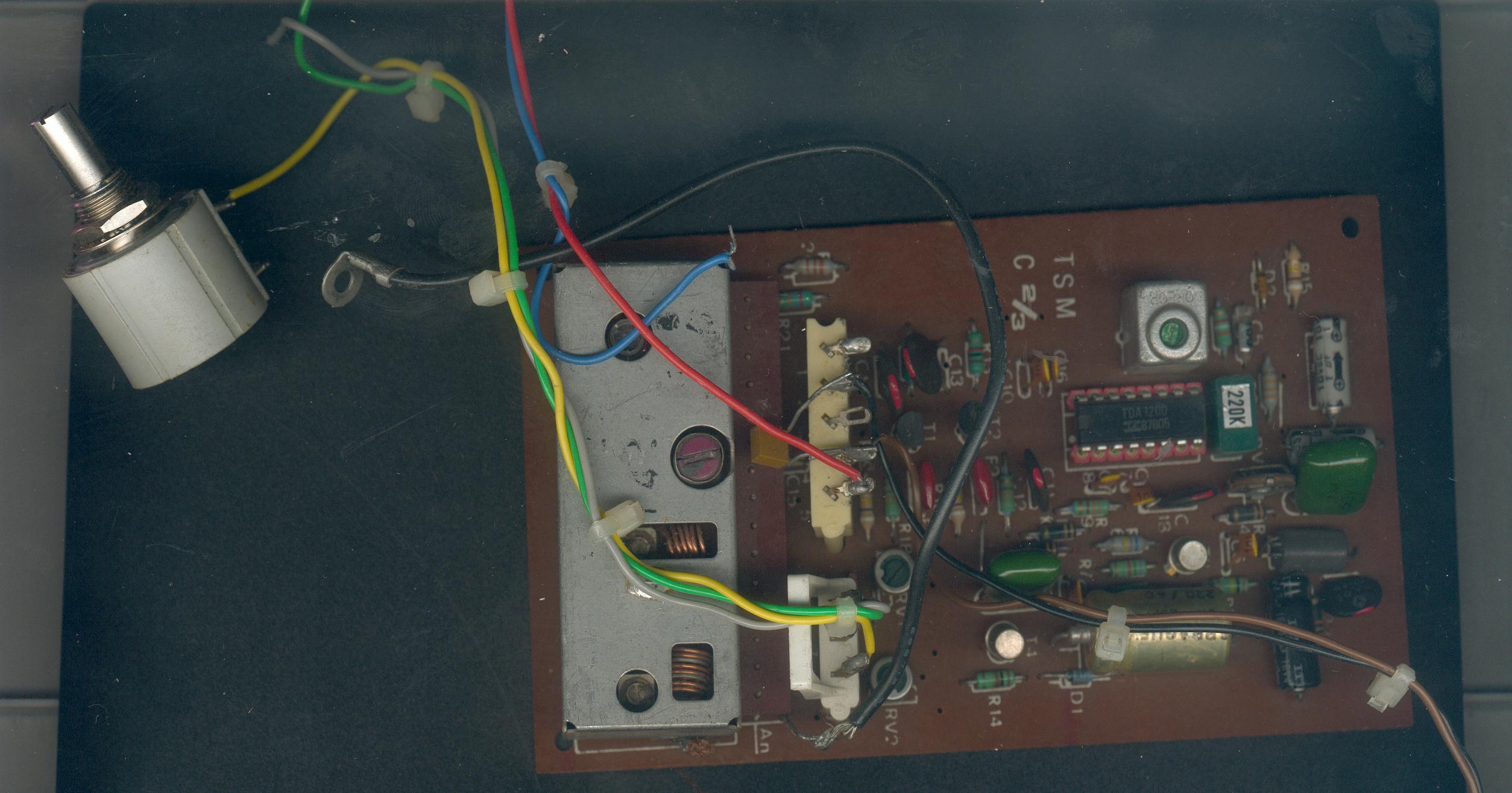
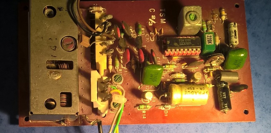
Tuner FM à varicap kit TSM31 FM Varicap Radio Receiver circuit TDA1200
CA3089E FM IF-Amplifier and Discriminator
Similar to AN377 LM3089N HA1137 TDA1200 KB4402 and TCA3189
http://www.retronik.fr/revues/electronique-pratique/1981/EP034_01-1981.pdf See page 54-55

![]()
A http://www.ariel.ac.il/sites/yosip/MPX_Stereo_SCA-FM_Tuner.pdf
![]()
http://www.emgo.cz/www_fa/Megahertz_11.pdf Récepteur FM pour la bande 137-141 MHz (1ère partie)
http://www.emgo.cz/www_fa/Megahertz_12.pdf Récepteur FM pour la bande 137-141 MHz (2ème partie)
![]()
http://electronique.marcel.free.fr/Recepteur_FM_miniature.html Récepteur miniature à TDA7088
![]()
http://www.py2bbs.qsl.br/tda7000_fm_receiver.php TDA7000 FM receiver
http://www.sparkfun.com/products/10227
SI4735-C40-GU AM/FM Radio IC
http://www.lextronic.fr/P5225-mini-platine-recepteur-fm.html cette petite platine exploite un module à base de circuit"AR1010" d'Airoha™. Ce circuit permet la réalisation d'un récepteur radio "FM" pilotable via un microcontrôleur externe au moyen d'une interface I2C™ ou SPI.
http://www.radiomuseum.org/r/saba_meersburg_automatic_7.html
![]()
http://hem.passagen.se/communication/fm_lcd.html digitally controlled fm tranmitter with 2x16 char. lcd display
![]()
FM BUG
spy microphone circuit : These are usually a one transistor LC oscillator on
the FM broadcast band. The microphone is audio amplified and slightly amplitude
modulates the base bias or the collector voltage. This produces both AM and
FM.
http://members.tripod.com/xexorz/schematics/fmtrans1.html Basic FM Transmitter , also other designs.
http://www.aaroncake.net/circuits/phonebug.htm
If you want to build a telephone fm bug
http://www.talkingelectronics.com/html/FM-BugsIntro.html
--------------------------------------------------------------------------------------------------------------------------------------------------------------------
Here is one of my favourite designs. It is very stable and VERY sensitive on the mic pick-up. It can be made very small as you can see from the picture. It uses 2 common 1N4007 diodes to act as varactor diodes.
It was designed to operate from a 9v batt but will work all the way up to 15v or so. The RF output was measured at 10mW on a spectrum analyzer with a 9v supply and increasing to about 100mW with a 15v supply.
Make the antenna wire about 32" long
The inductor L3 is about 5-6 turns of 22 gauge wire on a 0.1" former (like drill bit etc.) L1 can be common moulded type 1-1.5uH (Value not critical)
The transistors are CATV RF transistors from ON semi or Fairchild. You can try other devices but these really work well.
This works in the 88-108MHz band
----------------------------------------------------------
Here You have a good microspy schemes and instructions.
pcb and isntructions [ polish] , microspy
scheme
http://braincambre500.freeservers.com/rf%20amplifier.htm Build This AM-FM Radio Frequency Amplifier
See Also http://braincambre500.freeservers.com/ for various Radio , audio projects
http://www.broadcast.fr.fm Emetteur FM 87.5 108
http://www.pablin.com.ar/electron/circuito/radio/stereotx/index.htm Emetteur F.M. Stéréo Miniature à base du circuit BA1404
![]()
Inductances sur circuit imprimé: le logiciel gratuit dynamicshem de
Mr Lacoste à :
http://www.geocities.ws/robert_lacoste/freewares.htm
![]()
single ic radio receiver chip? Low cost?
for the lowest cost alone. just call or write each of these three, and say,
I need so and so, and I am selecting only on lowest cost". Review the quotes,
that you may get in your neck of the woods. Select cheapest
Toshiba's TA31275FN
http://www.toshiba.com/taec/press/to-302.shtml
Philips' TEA5767/68 TEA5757H
http://www.semiconductors.philips.com/markets/computing/pda/fmradio/
Atmel' T4258
http://www.atmel.com/dyn/products/devices.asp?family_id=637
http://www.winradio.com/home/receivers.htm cartes pour PC de "reception radio"
Le Récepteur FM Auto Scan Radio Palito PA-298 utilise le circuit SC1088 de SILAN Semiconductors. Remarque ce circuit peut aussi être utilisé non pas en Auto Scan mais avec un condensateur variable. Le schéma d'application est donné dans le datasheet. Je crois que ce circuit est semblable au TDA7088T de Philips.
http://hamradio.online.ru/sch_eng.html schemas pour tous les passionn�s de cb radio etc..
Radio RS232 Tranceivers
http://www.radiometrix.co.uk BIM3 modules - quite cheap and very easy to use.
Linx Technologies, if you prefer a one-peice tranceiver module rather than
a separate receiver and transmitter. Takes TTL level input. I ordered mine
from digikey ($40-$50). This uses the 900MHz band.
specs:
http://www.linxtechnologies.com/ldocs/modules/m_scp.shtml
http://www.glolab.com/tm1modules/module1.html
The people in this robotics lab have used Rs232<->DECT modules with success (see http://www.rcs.ei.tum.de/research/rovi/lpi2.html , there is not much technical info there, but it contains contact addresses for the people who built that robot). However, I think the DECT modules were somewhat expensive.
http://www.mikroelektronika.co.yu/english/product/books/rrbook/rrbook.htm Some basic FM receivers
http://www.midnightscience.com/ Dedicated to once again building and experimenting with radio electronics.
http://radio.meteor.free.fr/yagi_fm.html Construire une antenne YAGI FM Suite aux fr�quentes demandes sur le sujet voici par le menu et l'image la construction d'une antenne Yagi calcul�e pour la bande FM 88 - 108 MHz. Le fr�quence centrale utilis�e pour nos calculs est de 100MHz. Vous pouvez facilement extrapoler pour d'autres fr�quence grace aux valeurs des sch�mas ci-dessous. Cette antenne est moins difficile � construire que celle pr�sent�e sur la page pr�c�dente.
Inductor vs. Ferrite Bead
The ferrites:
http://www.panasonic.com/industrial/components/pdf/ex005_exc_cl_ml_3b_dne.pdf
The inductors:
http://www.panasonic.com/industrial/components/pdf/
el006_elj_rf_re_nd_nc_na_fc_fa_fb_sa_pe_pc_pa_ea_dne.pdf
In the case of the Panasonic inductor, I've been using their datasheet information
(including SRF and DCR) to model an inductor as a tank with a
series resistance.
For the ferrite model I used a tank with a parallel resistance. The source
for the model is
http://www.pspice.com/upload/appnotes/PSPA028.html#PSPA029_Figure2
Now, obviously, this model is for through-hole devices of a specific type.
What I've learned from the excercise is that parasitic capacitance is pretty
much the main differentiator between ferrites and inductors. Panasonic does
a poor job of providing data and applications' info on their ferrites, but Murata
does a lot better. I a now studying their three-terminal devices to
see about using them.
I'll trust a model as far as I can throw my (desktop) computer. But they are
useful in getting a tangible sense for how things work. The curves I've
been producing don't look significantly different from anything I've seen in
the manufacturer's data sheets ... which makes you wonder ... do they
measure or simulate?
http://www.pspice.com/upload/appnotes/PSPA028.html#PSPA029_Figure2
I found this page useful:
http://www.pspice.com/upload/appnotes/PSPA028.html
http://f4hla.free.fr/ Site Radioamateur
http://www.realfm.nl Plans for the 88-108mhz pll, stereo, stereo coder, antenna,slim jim, jpole, dipool, free, transmitters, 10ghz
RF Microwave Tools
--------------------------------------------------------------------------------
9705-1.pdf Diode Model Parameter Extraction from Manufacturers' Data Sheets
9708-1.pdf PIN Diode Model Parameter Extraction from Manufacturers' Data Sheets
dbm.zip Displays RF power and voltage realtions
network.zip Either an AC network analysis or RF design tool
pll.zip Phase-locked loop designer
rcalc313.zip Wireless RF Performance Evaluator fo WIN3.11
rf-coil.zip Single/multilayer coil designer
rfprop.zip Radio Propagation Calculator
rfs.zip Radio-frequency design program
rfsafety.bas Basic source text file for new FCC RF Safety guidelines
rftbox.zip RF CAE Tools
rftool1.zip RF design tools
tunekit2.zip RF / IF Bandpass filter circuit & coil design program
smithcht.zip Smith-chart program
radialwg.m radialwg.m is a MATLAB program that calculates the losses in a radial waveguide as a function of radial distance. Needs MATLAB ver4.0 or later
filter.mcd In this MATHCAD7 file, Betty Boop demonstrates low pass, high pass, bandpass and band notch filtering algorithms based on raised cosine transfer functions in the frequency domain. These may be applied to both real and complex (e.g. I+jQ) time sampled data. A simple cosine based window function is also included to demonstrate amplitude resolution improvement when slightly non periodic signals are processed. Uploaded by the author, Ian Scott.
Ascps11.zip This program is written to provide an ease in the quasi-static analysis/synthesis of SYMMETRIC CPS lines based on conformal mapping method. It is able to take care the finite thickness of the dielectric used and provides the option of including the effect of metallization thickness.
arpeggio.zip Arpeggio is an advanced Time-Domain Full-Wave Electromagnetic simulator. It solves the Maxwell Equations in time domain and find the desired frequency quantities via Fourier Transform.
quickcalc.exe A tool created to assist RF designers in making fast and accurate calculations for all essential capacitor performance parameters.
attenuator.xls This software calculates exact resistor values for PI, Tee, and balanced networks. Uploaded by James Phelps Jr.
coil.exe This program calculates the number of turns needed for a given inductance.
coilcal.zip Coil calculator
AC1009WD.EXE EasySpan for Windows can store, display and manipulate spectrum analyzer data from a variety of IFR products. The software serves as an excellent documentation tool for many applications.
eeref15.zip Convenient collection of engineering equations, conversions and references. Math tables, standard resistor values, periodic table, SAE & metric bolts, solder types, filter equations, coax cable specifications and many more. Over 150 windows. Uploaded by Kirt Blattenberger, the copyright owner.
ezguide.exe This Windows?based Microwave Transmission Lines software guides the design and ordering process. The exact component type, waveguide size, flange types, component dimensions, operating frequency band, and finish can be specified with point-and-click options. Each product is pictured on screen and diagrammed for your reference. Each rectangular waveguide component and its flanges are identified by a type number that is automatically created as you specify how each section should be configured. Last updated on 22 March 22, 1999.
final_zip.exe It will analyze multilayer transmission lines using the quasi-static variational technique.
towar.exe TOWAIR may be queried based on a specific set of coordinates, elevation and overall height criteria to calculate whether an antenna structure under 60.9 meters (200 feet) will penetrate the slope for nearby airports.
frqrsp.exe A utility that draws Bode frequency response plots.
gagetrol.exe Gauge calibration and GRER (repeatability and reproducability) software.
ilca210.exe This software calculates the attenuation or insertion loss of Andrew HELIAX coaxial cables.
inphorm.exe This software package is a fast, easy system which guides users to the best choices for EMI shielding/grounding and thermal interface materials among thousands of Chomerics products.
intermod.zip Calculation of Intermodulation Products up to 5th Order. Uploaded by Fritz Dellsperger.
int-mod.exe This program calculates all IntMod's by frequency.
LCMatch.exe An impedance matching calculator. You specify the real and imaginary values for the source and load, specify the frequency of interest, and LCMatch calculates all possible two element matching networks, (LC, CL, CC, LL).
linesim.exe PC board designer and line simulatorzip
MicrostripHousingResonances.mcd Mathcad: resonance Calculates resonant frequency of a housing partiall filled with a dielectric material. Uploaded by the author, Evan Kurtz.
mix_spur_ana_rev_1_1.xls This program calculates mixer intermodulation products upto 5th order and displays graph in amplitude vs. frequency. Use the amplitude level as a guide instead of absolute spec. The program is written in Microsoft Excel 97. Last updated in March 2000
mm_uli.exe MultiMatch is a software package which allows you to design state-of-the-art, first-time-right RF and microwave amplifiers (class A, B) in an integrated environment. MultiMatch microLite is a lumped-element impedance-matching utility (limited to three elements maximum).
mwpath.exe Lotus 1-2-3 worksheet to calculate the path of a microwave.
pathloss.exe PathLoss This program calculates path loss.
power.zip The PowerAnalyst plots and saves Voltage, Current, Power, Vars, Phase Angle, Distortion, Frequency, Volt-Amperes, and Power Factor.
receiver_simulator.zip Receiver Simulator In addition to being a tool for the design of communications receivers, this program might be useful as a tutorial on some of the aspects of receiver design; it includes explanations and definitions that are probably more detailed than the average user might require. This program should run under Windows '95, or later. Manual in .doc is included. Uploaded by the author in August 2000.
rxw.zip Receiver Workbook Cascade budget calculation spreadsheet for MS Excel. Complete parameter specification including Gain, NF, IP2, IP3, NBW, VSWR, Temperature, Tolerances. Predefined graphs for all parameters, parts list, DC power budget, A/D converter calculations. Uploaded by Kirt Blattenberger, the copyright owner. Updated in August '98. RF Cascade Workbook, an enhanced version of Receiver Workbook is also available for download on the site.
rfcw1p0.zip RF Cascade Workbook RF Cascade Workbook is a comprehensive set of tools for calculating cascaded parameters using advanced features of the MS Excel spreadsheet program. Extensive stage-by-stage calculations, graphing of min/nom/m@x values, and numerous calculators makes this an indispensable tool for the RF system designer. Uploaded by Kirt Blattenberger, the copyright owner.
rfmatch6.zip RF Match Graphic Impedance Calculator Version 6 This graphic impedance calculator can be used to match sources to loads with networks made with impedances, inductors, capacitors, transmission lines, stubs and transformers.
rfpw1p0.zip RF Project Workbook features MS Excel worksheets for project scheduling (Gantt Chart style), parts lists and procurement tracking, and system power supply requirements. Uploaded by Kirt Blattenberger, the copyright owner.
rfsyscalc.zip RF System Calculator This is a excel spreadsheet that analyzes cascaded stages in Receivers and Transmitters. The cascade analysis includes Noise Figure, Gain, intercept point, power input/output, SNR (in a given bandwidth), etc. A main signal can be present as well as a pair of interfering signals for analyzing off-channel IM3 rejection simultaneously. Simple AGC functionality is included. Updates are available at http://home.rochester.rr.com/lascari/rfsyscalc.zip. Uploaded by the author, Lance Lascari.
rfc_15.exe RFC An impedance calculator for RF design engineers.
RFCAD.ZIP RFCAD Several RF CAE Tools
RFP103.zip RFPROP Version 1.03 A Windows propagation calculator for the transmission path between an RF transmitter and a receiver. It is aimed mainly at free-space and space-wave applications, such as are encountered in VHF, UHF and microwave communications, and also in satellite communications. Updated June 24 1998.
rfsv202.exe RFS A program for Broadcast Engineers. Inculdes utilities for antenna design, frequency analysis, and circuit design.
schart.zip SCHART Smith Chart impedance matching program. Starting with any complex load impedance, select any type of matching network, choose a component value(s), then the program will list your new impedance.
smith_v191.zip Smith Chart Advanced Smith Chart with S-Parameter import/export, stability-, gain- and noise-, Q- and VSWR-circles. Last updated in July 2000. Uploaded by Prof. F. Dellsperger.
schrt.exe Smith Charting with Stability and Noise Circles It charts stability and noise circles.
sl60b.exe Sonnet Lite Sonnet Lite is based on the proven Sonnet em?Suite which is providing EM analysis to hundreds of companies across the globe. Many major manufacturers of high-frequency components and boards depend on Sonnet to analyze their predominantly planar high-frequency designs from 1 MHz through several THz.
sp_v2.exe Spectra is a FREE software package which allows you to view the spectral content of any time based data sequence. Spectra uses a Discrete Fourier Transform algorithm to convert time data into discrete frequency data, and then scales the discrete frequency data to generate the magnitude and phase of the frequency spectrum.
dsprf5.zip & dsprf7.zip A breakthrough for simulation and analysis of
RF and microwave circuits. Providing both linear and nonlinear circuit simulation,
Spectre/XL uses an enhanced harmonic balance algorithm to accurately analyze
circuits that are "too tough for SPICE".
Spectre/XL for MS Excel 5.0--->dsprf5.zip
Spectre/XL for MS Excel 7.0--->dsprf7.zip
spur.zip Spur Search
spsetup120.exe SPview 1.20 SPview is an S-Parameter toolset for RF and Microwave
engineering. With built in GPIB capabilities, it can capture data directly from
Vector Network Analysers and produce S-parameter files compatible with all major
simulators. Built in charting and data manipulation features enable faster circuit
design, the 2-port functions charts are particularly useful for amplifier designers
often removing several measure/simulate cycles.
Version 1.20 now includes built in time domain reflectometry (TDR) functions
to post process S-parameter data into distance to fault charts, a new VSWR chart,
the ability to merge data files, quick capture mode and an updated interface.
Last updated in July 2000.
tranT.exe Trans-Tech Resonator and Coax Design Program
line.zip Transmission Line Calculator Analysis/Synthesis of various transmission line structures. Uploaded by Fritz Dellsperger
transtek.exe Transtech Windows-based CAD and Transtech parts selector guides for dielectric resonators.
linecalc-1_00_win.zip ViPEC-2.00/LineCalc for Windows
waveformer.exe WaveFormer Pro v4.0
It is the first EDA tool to incorporative Interactive Simulation (HIS) technology.
vipec-static-1_07_tar.tar & vipec-1_00_win.zip & vipec-2_00_win.zip
ViPEC is a powerful tool for the analysis of high frequency, linear electrical
networks. It takes a text based description of the electrical network and an
analysis is performed in the frequency domain. The output is in the form of
2-port parameters (S, Y or Z) with results presented on a user defined grid
and Smithchart. It can also be used to compute the input and output impedance/admittance
as well as amplifier stability factors (Linvill & Stern).
vipec-static-1_07_tar.tar(ViPEC for Linux)
vipec-1_00_win.zip(ViPEC for Windows 95)
vipec-2_00_win.zip(ViPEC-2.00 for Windows)
example : :when youwant to download "9705-1.pdf" the url is shown above: Code: http://rf.rfglobalnet.com/downloads/9705-1.pdf
http://members.tripod.com/~transmitters/links.htm Radio kits FM Transmitter schematic hobby broadcast RF Circuit Antenna Surveillance spy Links for FM Transmitter Kits, Circuits, Electronics ...
FM Radio with the self tuned radio TEA5757
http://mujweb.atlas.cz/www/pira/fmcards.htm
http://openbsd.secsup.org/src/sys/dev/ic/tea5757.c
http://openbsd.secsup.org/src/sys/dev/ic/tea5757.h
It is very difficult to give you any specific advises as you do not give out any details on the specifications of your intended design.
There exists numerous ways of designing a radio, some with good points in some
aspects, vice versa for others. The way I would start in designing a radio having
a particular chip in mind intended for the purpose, would be to look for any
application notes that the manufacturers might have. Such often contain useful
information,
circuit examples, formulaes etc.
Do not forget to check whether the chip may have alternative manufacturers
(they may have additional application notes) and also whether there might exist
any close equivalents (functionally).
Sometimes different manufacturers make chips that are not exact equivalents
but quite close. Locating such (if they exist) may give you still more sources
for application notes that in turn could give you more good ideas and examples
of useful design approaches
http://www.ginko.de/user/franz.hamberger/roehren/roehren.html The Tubes and Valves Online Database
http://www.hobbyelectronics.net/con_fm-transmitter.html Build a simple FM transmitter
http://perso.orange.fr/f6crp/elec/index.htm Traité d'électronique pour le radio amateur
http://radiomods.free.fr/ Modifications de Radiotéléphones
Philips Application Note AN192.pdf
Philips Application Note AN193.pdf
http://www.nxp.com/documents/data_sheet/TDA7000_CNV_2.pdf
![]()
RDS
rdse2t décodeur rds pour carte mini-terminal 68hc811e2
http://ulegan.de/rds/picrds.htm
décodeur RDS à base du TDA7330 et du PIC16F84
http://www.anotherurl.com/library/rds.htm
http://www.pira.cz/index.htm
http://www.pira.cz/eng/index.htm
http://members.lycos.nl/rdsencoder/rds1.html
http://mujweb.atlas.cz/www/pira/rdsschem.htm
http://www.mujweb.cz/www/pira/rdscze.htm codeur RDS
http://www.qsl.net/dk7in/RDS.html
http://www.rds.org.uk/rds98/rds98.htm
http://www.esslinger.de/rds/rds.htm
http://members.home.net/lsnwnn/bill/rds/rds_home.htm
http://www.semiconductors.philips.com/pip/SAA6588/V2
http://www.tmcforum.com/technic/compendi/rdsoverv/rdsovcon.htm
http://www.techbooks.co.uk/artech/book397.htm
http://www.audemat.com/download/FM_subcar.PDF
http://www.semiconductors.philips.com/pip/saa6588t/v2
http://www.daisy-laser.com/tunerkit_tn1.htm RDS Tuner kit using CCR921 Philips RDS Decoder microcontroller
http://www.rds.org.uk/rdsfnews17.html Philips Chipset for RDS Radio in a PC
http://www.tmcforum.com/technic/compendi/rdsoverv/rdsovcon.htm
http://www.techbooks.co.uk/artech/book397.htm
http://www.audemat.com/download/FM_subcar.PDF
http://www.radiomods.co.nz/integratedcircuits/componentspage.html Audio & RF Components page
http://f5soh.free.fr/ Site Radioamateur de F5SOH - modification des talco uhf par pic pour piloter deux pll (modif d'un radio telephone Nokia 620)
Récepteur VHF
http://www.cibinet.com CIBINET.COM
http://www.multimania.com/f1rhr/index/ Pages techniques Radio, liens, CD-ROM de l'atelier d'électronique by Fourtet(F1RHR) .
http://col2000.free.fr/vhf/vhf_indx.htm Magnifique récepteur aviation by Pierre Col.
Jordan RF Electronics Web Site Liens, projets dans le domaine Radio et HF
http://www.frpacket.org/ L'actualité du reseau packet radio amateur francais
http://hfmania.forez.com/livre.htm Emetteurs FM, codeur stéréo, etc..
http://www.ifrance.com/electroremy/elecemfm.htm petit emetteur fm
RadioTOP détecteur horaire : Ce petit montage était destiné au départ à détecter les Heures Pleine (HO) afin de mettre en route un Tuner au moment des informations puis de le couper environ 5 minutes après soit à la fin du flash. Mais à la réflexion nous avons décidé de mettre à dispositions diverses sorties que chacun pourra affecter à son gré (et à la seconde près) comme une génération de tops sur buzzer, une ligne audio prioritaire pour les quatre tops des heures pleines, des commandes de machines, etc. (D'après l'article RADIO-PLANS n�577 p.31-34 de Jean ALARY)
Ampli UHF/VHF
Micro Emetteur F.M. en CMS
Transmission de données Série en H.F. (D'après l'Article RADIO-PLANS n�577/p.49-53 de Patrice OGUIC)-Le mode de communication le plus utilisé pour la transmission de données entre micro-ordinateurs est sans aucun doute la liaison série, liaison disponible sur la quasi totalité des machines. Elle permet en effet des liaisons filaires sur quelques mètres sans augmentation notable du taux d'erreur de transmission. Il se peut malgré tout que la mise en place d'un câble de liaison puisse poser des problèmes pratiques. C'est pourquoi nous vous proposons un circuit simple qui permet de s'affranchir de cette ligne.
Emetteur F.M. 88-108 Mhz
Emetteur Radio sans bobinage
Technologie Bluetooth
: (2,45 GHz) - technologie de transmission sans fil d�velopp�e initialement
par Ericsson, IBM, Intel, Nokia et Toshiba au sein du groupement Bluetooth Special
Interest Group (SIG). Site Officiel
- Ressources technologiques.
Constructeur : Conexant
- Philsar.
sch�mas d'�metteurs FM:
http://members.tripod.com/~transmitters/links.htm
http://www.geocities.com/CapeCanaveral/Hall/8701/piralynx.htm
http://www.mycal.net/projects/mpr/index.html
             2   2
           a   n
     L = -----------
           9a + 10b
Accurate design of small single layer air-wound inductors for microwave
filters can be done using this free software. This is the PCAIRL program
described in RF design magazine, November 1994, page 52. New version 2.90
for Windows 95 with mouse control and integrated optional standard drill
bit size winding diameters (Oct. 1999).
2.Use "reci" or "spi" printed inductors in serenede
8.71, or "ind" for inductor, but COIL I trust ALKEngineering more
and it is free.
There are similar models in Genesys and ADS.
For coils use any coil software, measure and tune it on vector network analyzer, deembed model for wide bandwidth and use it in your circuit simulation.
http://hem.passagen.se/communication/aircoil.htm Air Coil Calculation This side will explain how to calculate coils and will explain how you can make your own coils. I have made coils with different number of turns and measured the inductance. See also resource at http://hem.passagen.se/communication/meny.html
New Windows version of best RF coil calculator:
http://64.130.134.245/saratogasoftware/aircoil.html
Emetteur F.M.
Sinon je te conseil vivement de te renseigner sur la réglementation
.
http://www.art-telecom.fr/
ou
http://www.admi.net/jo/
EMETTEUR RADIO
un emetteur radio est constitué pour la partie HF, d'un oscillateur
pilote oscillant sur la fréquence souhaitée et suivi d'un
amplificateur de puissance .
L'oscillateur peut être à quartz ou à synthétiseur
de fréquence :
---un oscillateur à quartz est généralement suivi d'un
étage multiplicateur qui permet d'utiliser les harmoniques grace
à des étages montés en cascade :
"doubleur" F.2 et (ou) "tripleur" F.3 pour obtenir des
fréquences élevées .
---un oscillateur à synthétiseur de fréquence est basé
sur un VCO :
"oscillateur commandé en tension", oscillant directement
sur la fréquence utile d'émission . Cet oscillateur possède
une plage de fréquence qui est fonction d'une plage de tension de
commande, par exemple F varie de 400 à 440 MHz avec une tension de
commande qui varie de 1 à 4 V . On pourrait l'utiliser avec un simple
potentiomètre variant de 1 à 4 V mais la précision
serait ridicule et les dérives en température impressionnantes
.
-La fréquence du VCO dépend donc de sa tension de commande,
laquelle est asservie par un système de boucle à verrouillage
de phase , c'est à dire une tension (amortie par un RC=filtre de boucle)
issue d'un étage "comparateur de phase" lequel compare d'une
part : la fréquence sortant du VCO (après division programmable)
et d'autre part : la fréquence fixe d'un oscillateur de référence
à quartz très stable : le TCXO (de fréquence relativement
basse par ex . 6,4MHz) . De ce TCXO depend la stabilité en fréquence
de l'emetteur . Quand la fréquence est identique de chaque coté
entrant du comparateur de phase, la tension de commande du VCO est stabilisée,
on dit alors que le synthétiseur est "verrouillé"
(lock) , le système est seulement utilisable à partir de ce
moment, et une info logique de verrouillage autorise l'émetteur à
emettre, ou le recepteur (oscillateur local à synthétiseur)
à recevoir etc...
La MODULATION
Un tel émetteur n'emet qu'une onde pure ne véhiculant aucune
autre information qu'elle même , pour transporter de la parole par exemple
, on doit effectuer une MODULATION de cet emetteur : pour moduler un emetteur,
on peut choisir de faire varier 3 paramètres :
a) la puissance (modulation d'amplitude AM )
b) la fréquence (modulation de fréquence FM)
c) la phase . (modulation de phase PhiM, equ. à FM)
On peut expliquer facilement la Modulation par une métaphore très
simple : la modulation AM ou FM est à la radio ce que les lumières
psychédéliques
sont à la boîte de nuit .
Si l'on fait varier l'intensité des spots en fonction du son d'un micro
d'ambiance, on obtient une modulation d'amplitude AM , si l'on garde un allumage
constant des spots, mais que l'on fait varier la couleur, on obtient une modulation
de fréquence .
RECEPTEUR RADIO
pour le récepteur je vais procéder par l'exemple : (il est préferable
de faire un dessin avec des carrés et des flèches chaque mot
entre guillemet étant un carré )
1) Une antenne capte un très faible signal ayant une fréquence
de par ex. 150 MHz . Ce signal est acheminé vers un étage
"tête HF" qui amplifie (un peu) et filtre (un peu) .
2) Ce signal est acheminé vers un étage "melangeur"
qui reçoit ce qui vient de la tête HF, et par ailleurs, le signal
haute fréquence stable provenant d'un "oscillateur local "
-OL- cet oscillateur est réglable ou programmable pour osciller sur
une fréquence de 139,3 MHz . Le résultat de ce mélange
150-139,3 donne une nouvelle fréquence de 10,7 MHz .
3) Ce signal de 10,7 MHz est ce qu'on appelle le signal FI (fréquence
intermédiaire) , cette valeur est fixe . Comme cette valeur est toujours
de 10,7MHz à ce point du recepteur , il est donc possible de placer
à la suite un "filtre raide" centré sur 10,7 MHz .
Ce filtre représente donc la véritable selectivité du
recepteur . Ensuite on amplifie très fortement et uniquement ce qui
est passé dans le filtre, dans un étage à très
très fort gain "l'amplificateur FI" (il est plus façile
d'amplifier à 10,7MHz qu'à 150MHz) .
4)Il ne reste plus qu'à faire suivre d'un étage "discriminateur
FM" si on veut démoduler de la modulation de fréquence
, ou un "detecteur AM" pour démoduler la modulation d'amplitude
, et retrouver la modulation audio de départ...
Si l'on veut recevoir 145MHz par exemple , il faudra programmer l'oscillateur local "OL" sur 134,3 MHz (145 - 134,3=10,7) .
le principe de reception que je viens de décrire s'appelle "superhétérodyne" . Ce principe du "changement de féquence" existe à peu près depuis 1917 , invention due à Lucien Lévy (ingénieur à la Tour Eiffel) . Ce que j'ai décrit est un récepteur "infradyne", c'est à dire que l'oscillateur local est determiné par une soustraction 150-10,7= oscillateur local de 139,3 . On peut aussi utiliser une addition 150+10,7=oscillateur local de 160,7 . C'est la réception "supradyne" . dans les deux cas supradyne ou infradyne , le résultat est identique pour la fréquence reçue et la valeur de la FI . La sélectivité de ce recepteur, (la faculté d'ignorer les autres signaux des fréquences proches et très perturbateurs) est essentiellement due au filtre à quartz ou céramique etc... qui débute la FI , c'est le grand interêt du superhétérodyne, en même temps que d'abaisser la fréquence reçue pour l'amplifier plus façilement...
http://www.gizmo60.fr.st petit emetteur FM 90-110 MHz
![]()
Télécommande radio codée à 4 canaux (Article Le Haut-Parleur n°1861 P.82-86 C.Tavernier) utilise le circuit ICP400 (Lextronic) et module récepteur AM à super-réaction Mipot pour le récepteur et circuit UM3750 ou MM53200 et module émetteur AM Mipot pour l'émetteur.
![]()
TDA7000N FM-receiver from A.Caristi (Poptronics october 2000)
![]()
Les modules Hybrides pour Emission-réception radio (Electronique Radio-Plans N°561 /P.41-45 - Patrick GUEULLE)
![]()
![]() 31 décembre, 2023
31 décembre, 2023
 matthieu.benoit@free.fr
![pcb and isntructions [ polish]](images/microspy1.jpg)