![]()
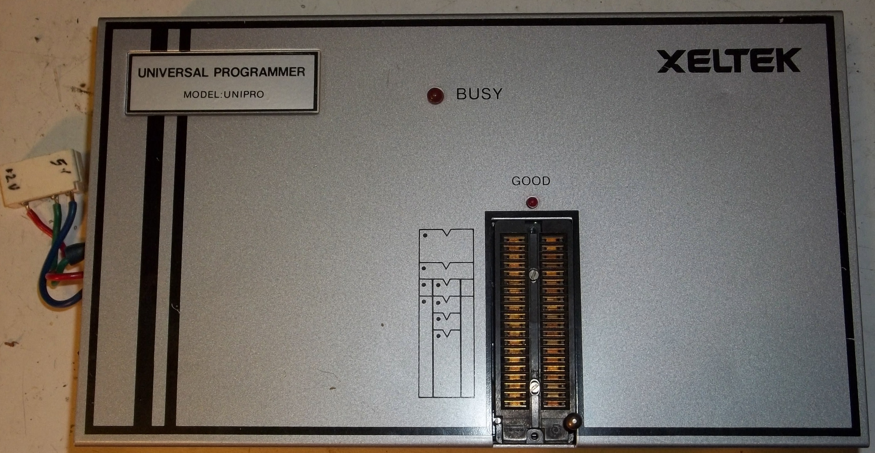
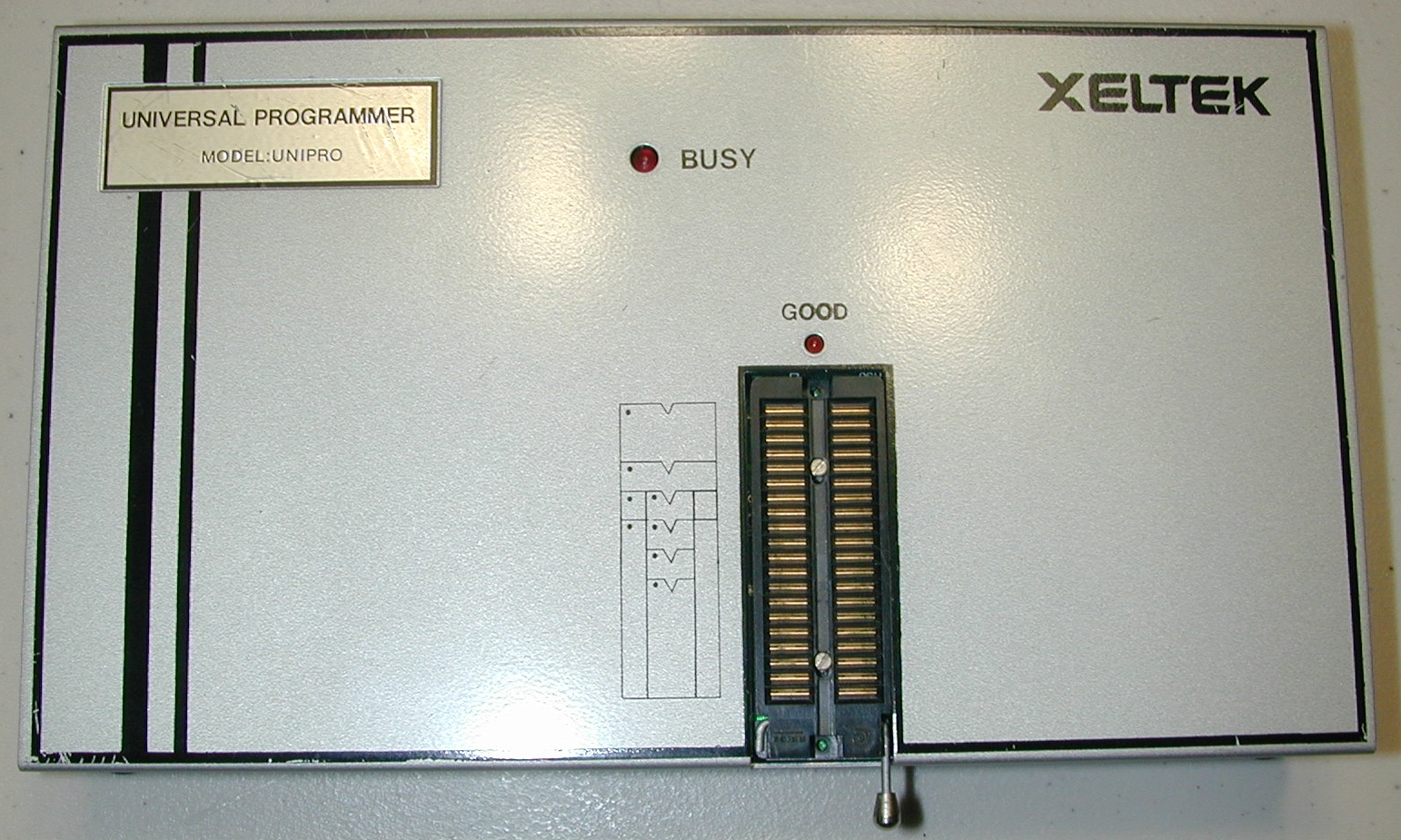
Programmateur Xeltek Unipro

![]()
This programmer needs a ISA interface card,
If you have any information about the ISA Card required thank you to contact me.
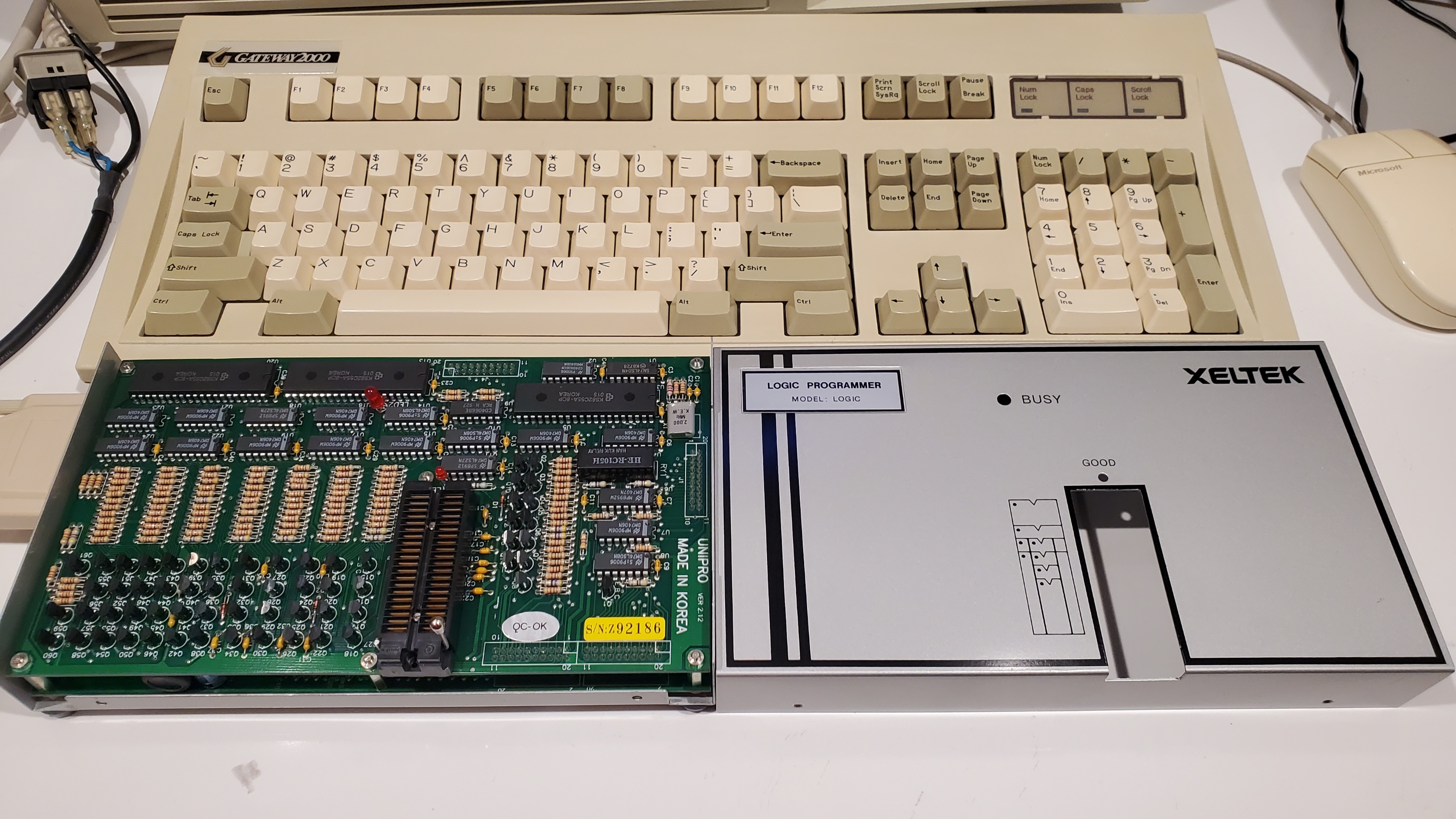
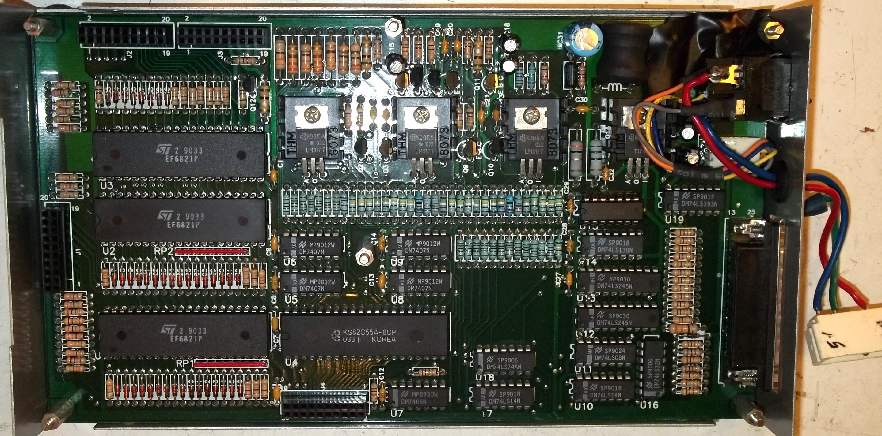
new_pcb to be tested (work in progress):


3 jumpers 5V version
this card has been tested OK with the Xeltek Unipro programmer
![]()
![]() Xeltek Unipro Users Manual
(PDF-77 pages -25.81Mb)
Xeltek Unipro Users Manual
(PDF-77 pages -25.81Mb)
![]() devices that can be tested with
the Xeltek Unipro: (.txt) use ICT software
devices that can be tested with
the Xeltek Unipro: (.txt) use ICT software
UNIPRO- liste des IC couverts par TTL.dat
7400-01-02-03-04-05-06-07-09
7410-11-12-13-14-15-18
7420-22-25-27
7430-32-37-38
7440-42-47
7451-55
7474-75-76
7485-86
7492-93
74107-109
74112-113-123-125-126-132-133-136-137-138-139
74146-148-151-153-158
74160-161-162-163-164-165-166-173-174-175
74190-191-192-194-195
74240-241-243-244-245-253-257-258-259
74260-266-273-280-283-293-299
74365-366-367-368-373-374-375-377-386-640
---------------------------------------------------------
4016-23-25-27-28-43-49-50-51-66-68-70-71-72-73-75-77-78-81-82
4501-03-06-12-18-19-32-72.
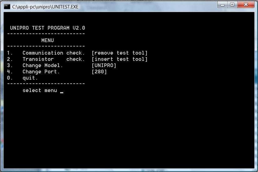
the programmer can be tested with the UNITEST software
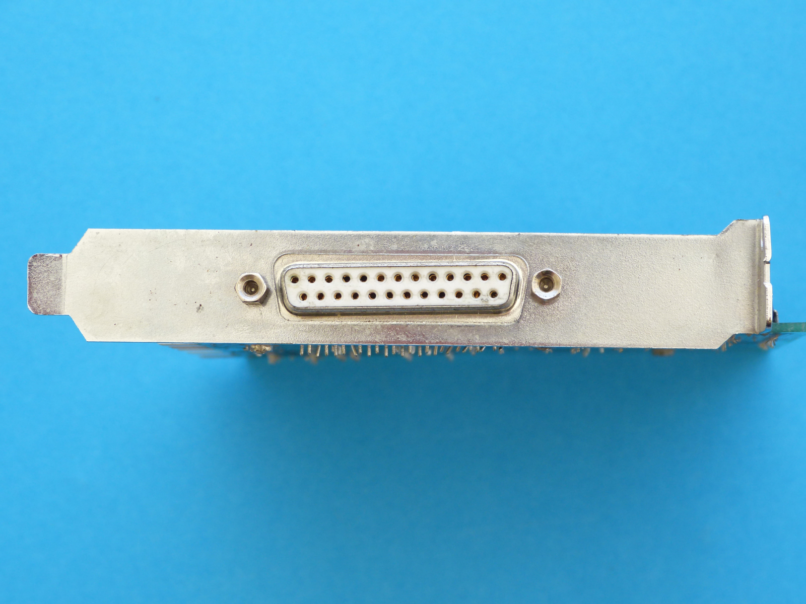
![]()
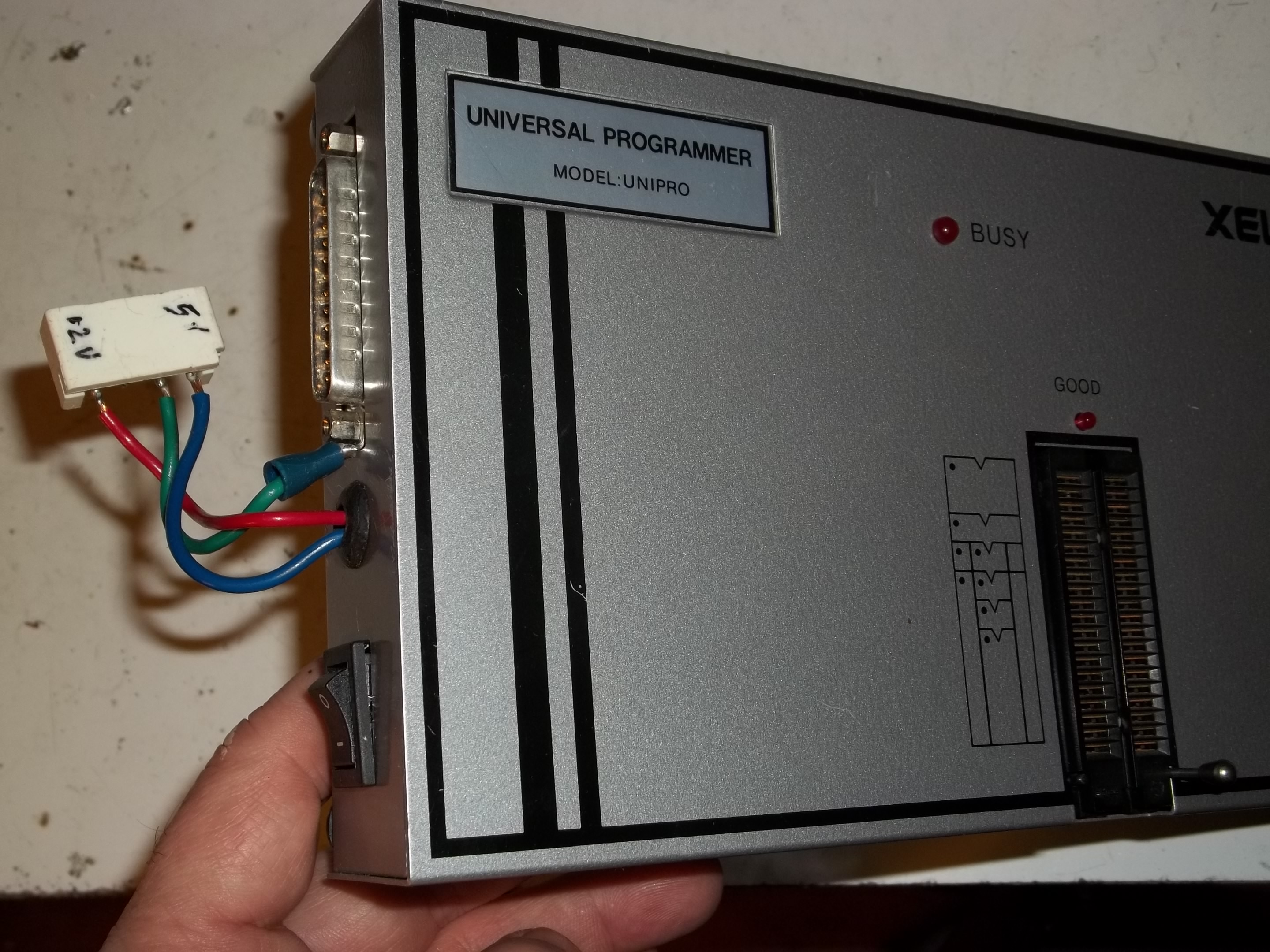
DB25M Connector on the side with on/off switch ;
pc power supply connector is just a hack to do some tests
![]()
The MS-DOS software for the Unipro is available from Xeltek site
Le logiciel DOS pour le Unipro est disponible sur le site de Xeltek https://www.xeltek.com/superpro-software-download-center/legacy-programmer-download-center/ bottom page
http://www.xeltek.com/software/splegacy/Dosunipro.exe
archive Dosunipro.exe (423Kb)
![]()
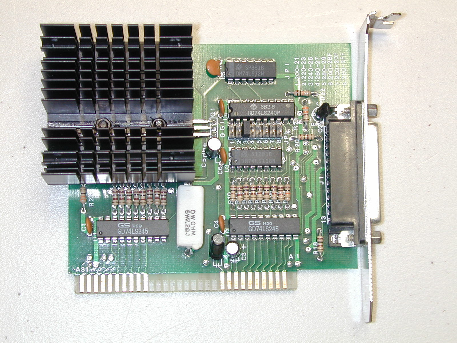
here after a photo of a ISA card perhaps for a Xeltek programmer?
If you have any details, thank you to help me.
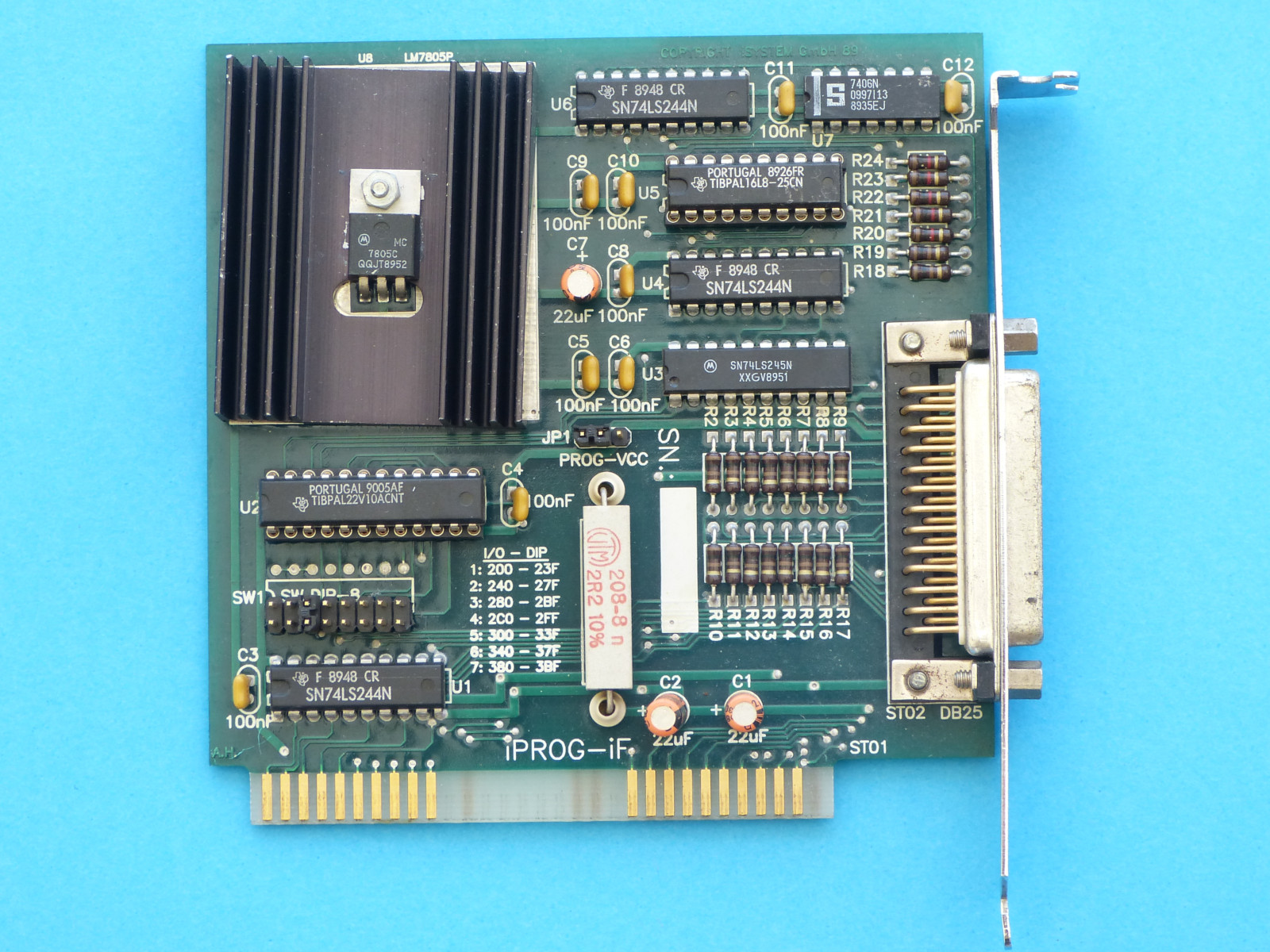
Although it is clearly the same design as the CSA-03/04 boards, I don't know
if Hi-Lo manufactured it or if Xeltek produced it themselves. There are manufacturing
differences which indicate that it was not made in the same factory as the CSA-03/04
boards (different method of cutting the PCB substrate, different mask, different
silk screen, different hardware). It's possible that Xeltek may have licensed
the design from Hi-Lo and then manufactured it themselves in their own facility
in Korea (either that or Hi-Lo had another manufacturing facility in Korea at
the time).
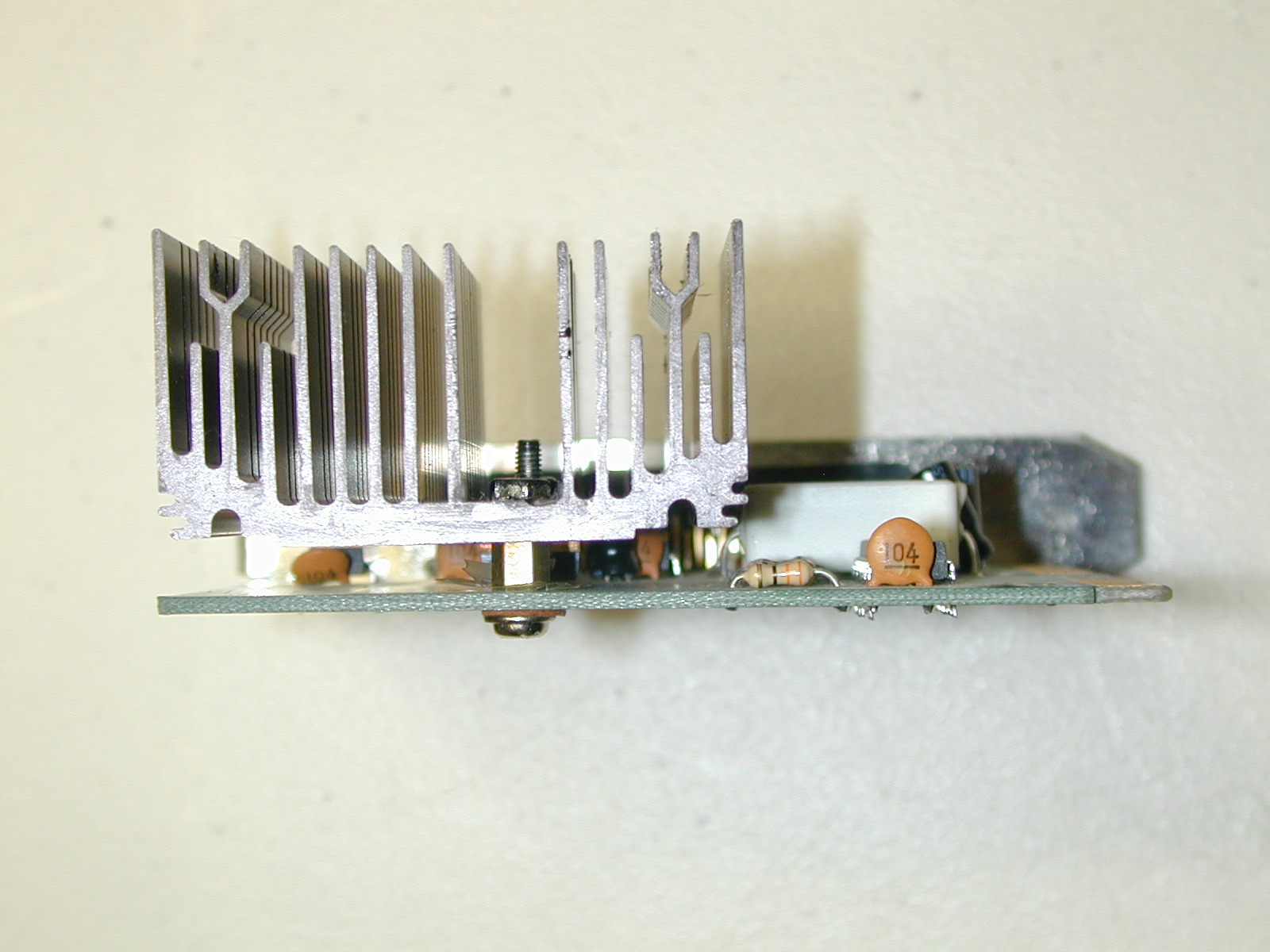
Note that when used with a Xeltek Unipro, the ISA interface board is even more in need of the heat sink modification (due to the heavier current draw of the Unipro over the MOD-MEP-4).
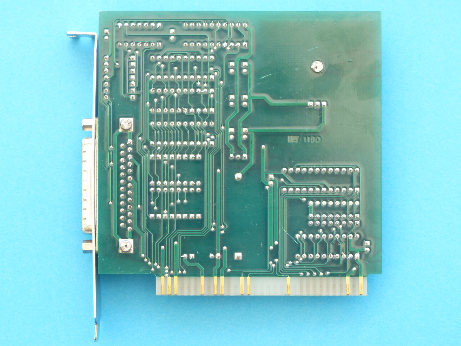
The modified board pulled from one of my programming systems to show the heat
sink modification that I made to all of the cards I use.
I found the original heat sinks on these cards to be marginal. They are adequate
under light use, but under repeated use, the boards get much too hot. The temperature
of the regulator can approach 70 degrees C (it's maximum operating temperature).
With the much larger heat sink, elevated off the board, pulling the heat away
from the PCB and providing extra air circulation, the temperature stays below
40 degrees C.


![]()

<click
to enlarge>
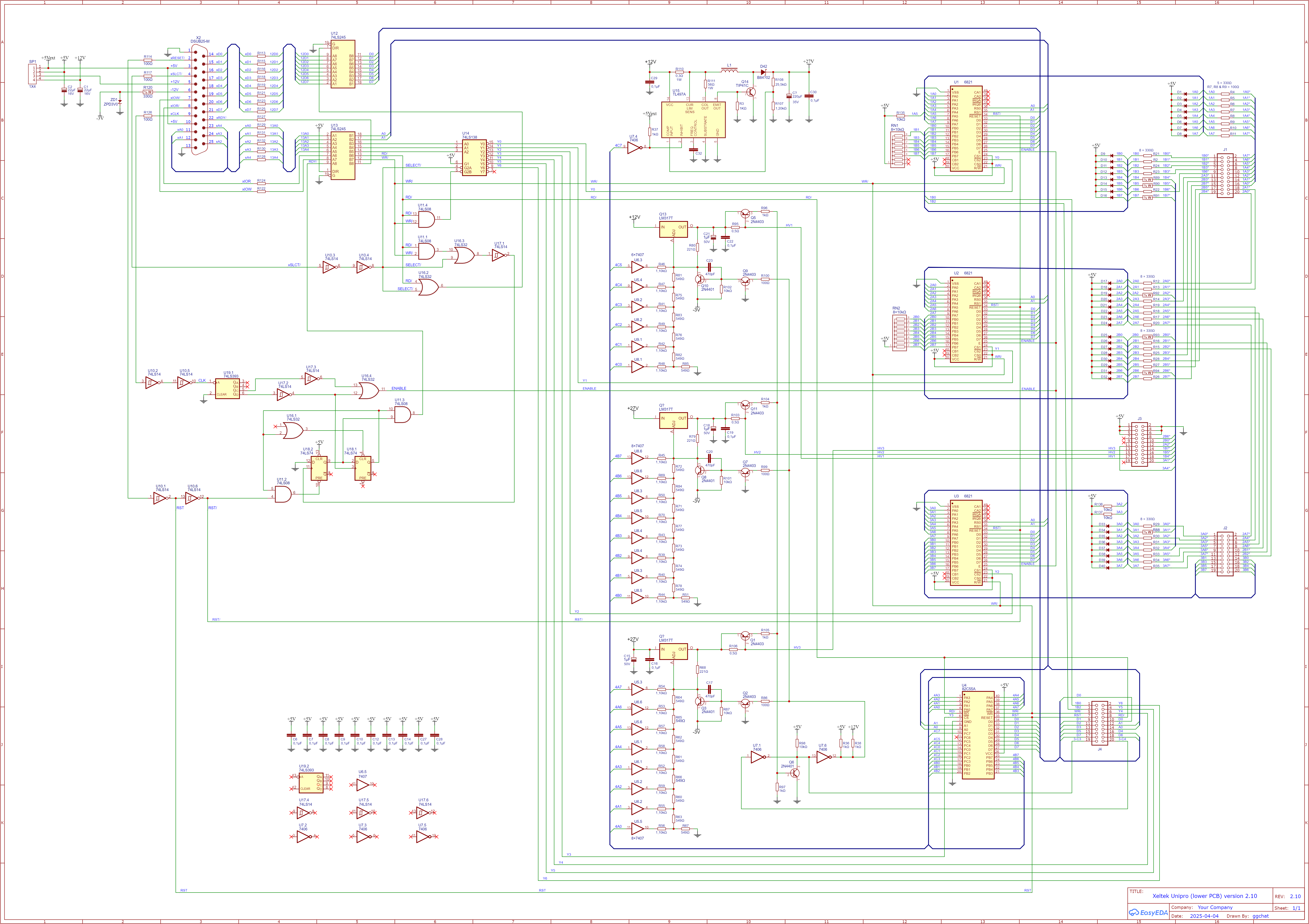
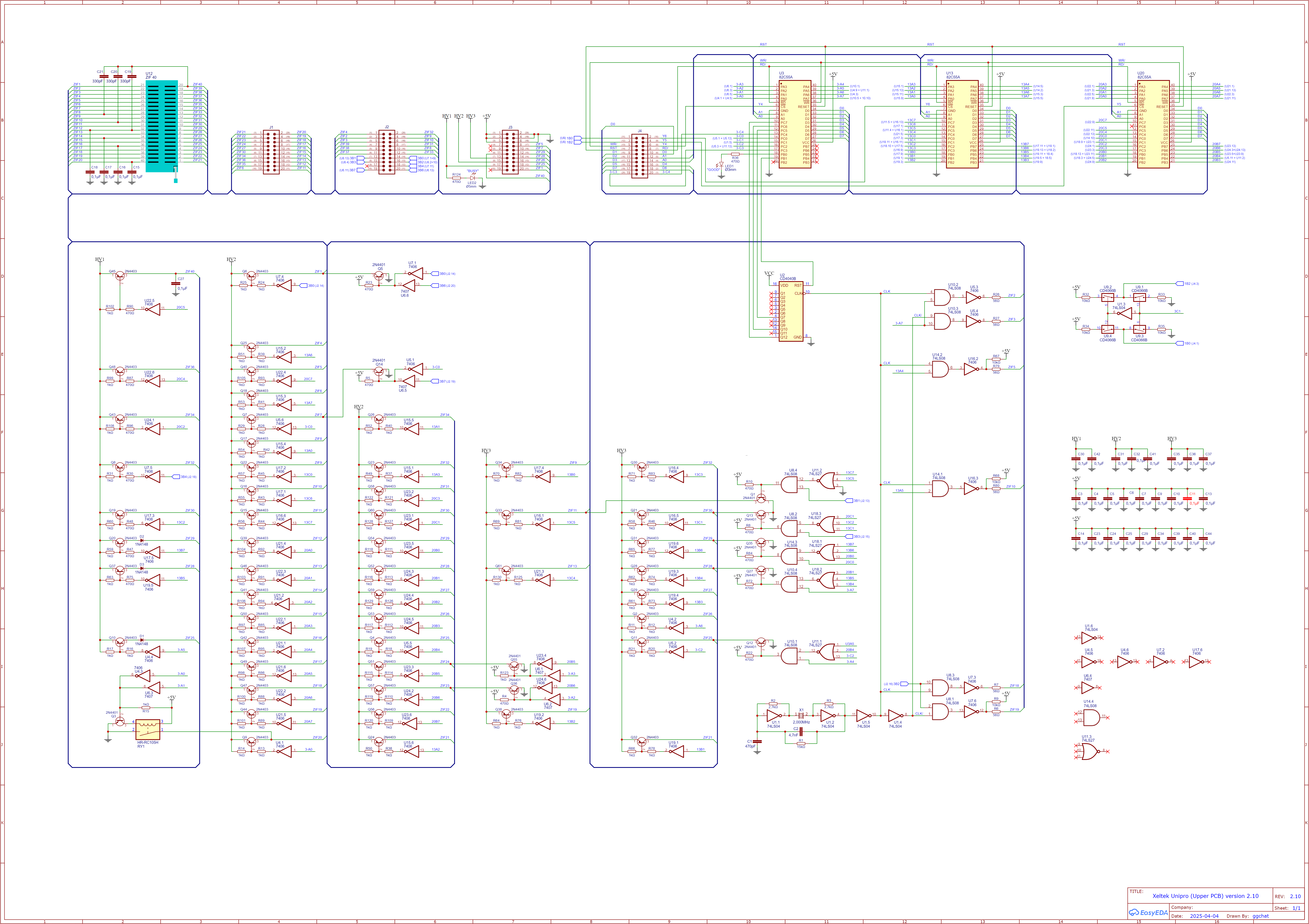
schematic ISA Card


shematic unipro (update April 2025) courtesy ggchat
 J2+J3
J2+J3
 J4
J4
photos showing the numbering of the different pins of connectors J1 to J4 between upper and lower pcbs.
odd and even side for J1 to J4 of bottom pcb as a HE10 connector.
numbering as ics pin numbering for the upper pcb
Photos showing the different numbering of the pins of connectors J1 to J4 between the screen printing of the lower and upper PCB's:
Even and odd rows for J1 to J4 of the lower PCB, as for a HE10 connector.
Counterclockwise numbering (as for the tabs of the chips) for the upper PCB.
pin 1 correspond for J1 to J3 (no photo for J1, it is the same numbering as
for J2 and J3), for J4 leg 1 corresponds to leg 20 of the lower PCB.
On this diagram and for these pins, is used the same numbering as that of the silkscreen of the lower PCB (as for a HE10 connector), the smaller numbers in brackets correspond to the silkscreen of this upper PCB.
Since there is an 8255 referenced U3 on each PCB, the pins of the upper 8255 are prefixed "3-" instead of "3" for the lower.
Note the contact of Relay RY1 on pin 20 of the ZIF support. The grounding of this pin (GND pin of the EPROM's) should not be reliable enough on the HiLo All-01 which must have determined the addition of this relay on the Xeltek Unipro.
![]()
notes : differences between hilo All-01 and Xeltek unipro
• The Hilo All-01 has 2 converters TL497 to generate programming voltages while the Unipro has only one that generate the 27Volts , Voltage(s) to be used to generate 3 different voltages with the LM317 and resistors
• the big black module on the ALL-01 might be used to generate the "E" (Enable) signal for the PIA's 6821 ; this function is done by U16 to U19 ICs on the Unipro which should indicate that the Unipro is a clone of the ALL-01 and not the opposite because on the first the ICs numbers are not attributed in function of the placement as it is the case for the already existing Ics but added after (16 to 19), Also U16 is placed 90° angle of the others
• concerning the other schematic there should be no other differences
![]()


Unipro test program
![]()
XELTEK Logic programmer
![]()


![]() LOGIC.ZIP (ZIP Archive - 106Kb)
LOGIC.ZIP (ZIP Archive - 106Kb)
![]()

![]()
*******
If you look forward for other information about this Programmer,
do not hesitate to contact me by e-mail at: matthieu.benoit@free.fr
.
Important Notice: Also if you have any data about this programmer, adapter diagrams,
do not hesitate to contribute to this page.
Si vous recherchez des informations pour ce programmateur, vous pouvez me contacter par e-mail : matthieu.benoit@free.fr . De même si vous avez des informations sur ce programmateur, n'hésitez pas à contribuer à cette page.
![]() 20 juin, 2026
20 juin, 2026


 Retour au sommaire
 Retour
à la Page d'accueil
Retour
à la Page d'accueil matthieu.benoit@free.fr