In the archive sac201.zip you
get the layout as tiff´s. (Zip Archive- 92Kb) - The large ones are for
information, one of these is not corrected. Printing with PaintShop Pro gives
me the correct size; but may be to correct a little bit in special case. The
CU-areas into the ISA slots must be soldered to get good contact over the
time with now erosion (not CU in AU-contacts).
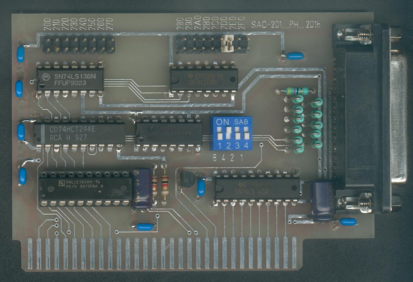
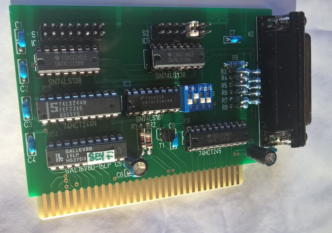
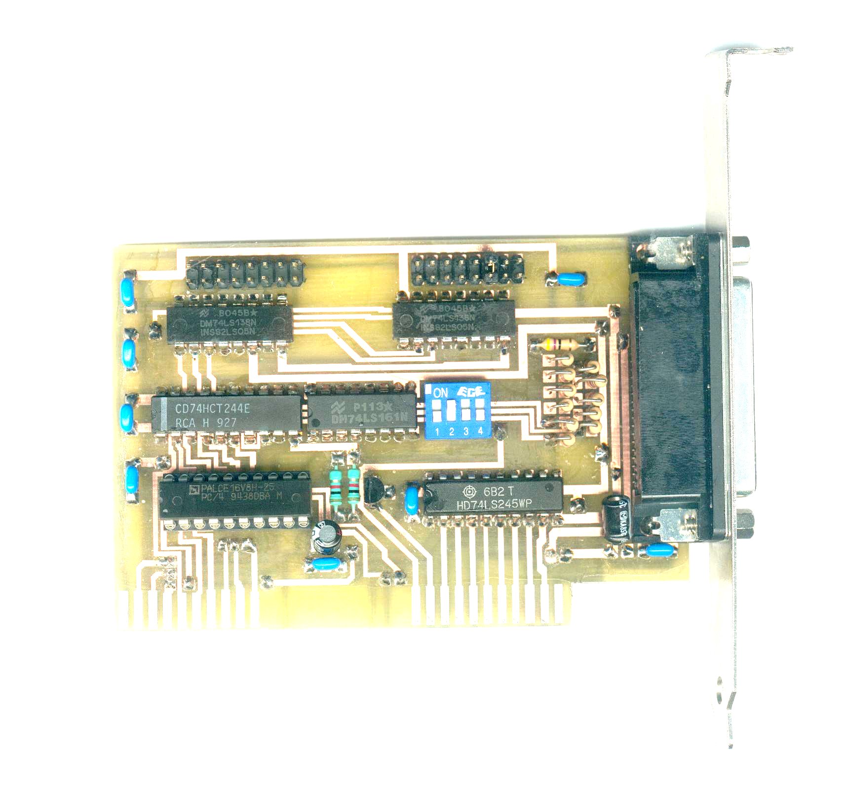
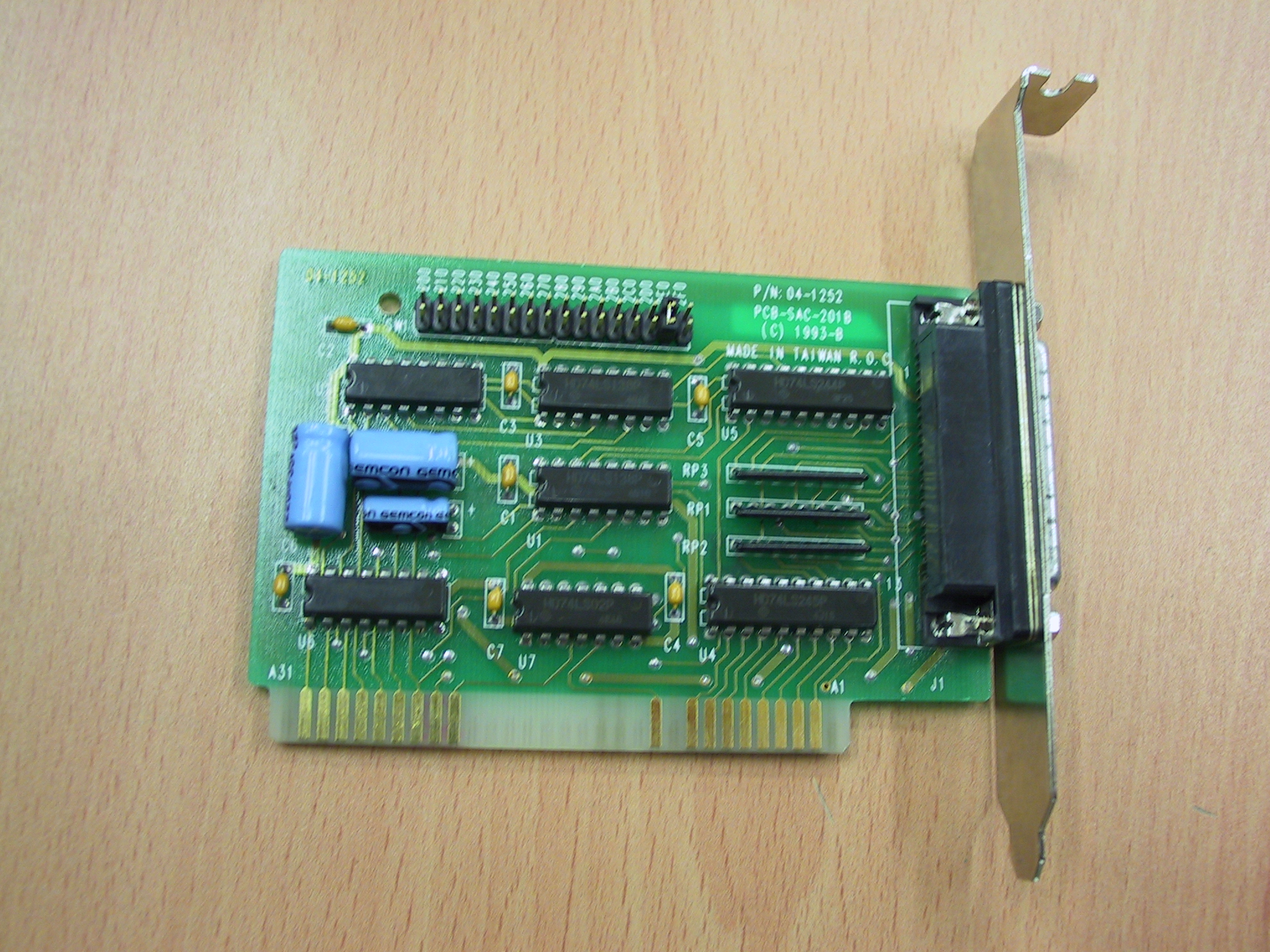
here you'll find the PCB of the SAC201 hilosystems board drawn by MITSUKO.
Bill of Materials of SAC201 board:
C2,C3,C4,C6,C7,C8,C10,C1 100nF
C5,C9 10uF
J1 IBMXT
J2,J3 HDR_16
J4 HDR_8
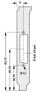
J5 DELTA_25HF
R1,R2 1K
R14,R3,R4,R5,R6,R7,R8,R9,R10,R11,R12,R13 47E
T1 2N4401
U2 74LS161A
U3 74HCT244
U4 PAL16V8
U5,U1 74LS138
U6 74HCT245
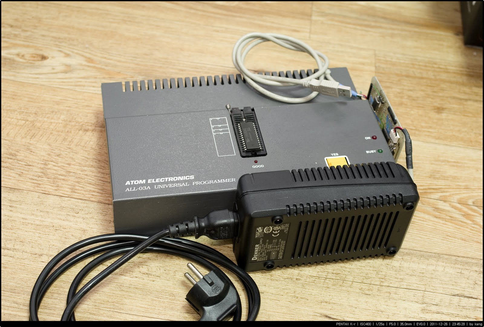
power ratings for a hilo all-03
Power: 5V - max. 0,5A (stand by) / max. 0,8A (aktiv)
12V - max. 0,3A (stand by) / max. 1,5A (aktiv)
-12V - max. 0,1A (aktiv)
Size: 262 mm x 142 mm x 45 mm
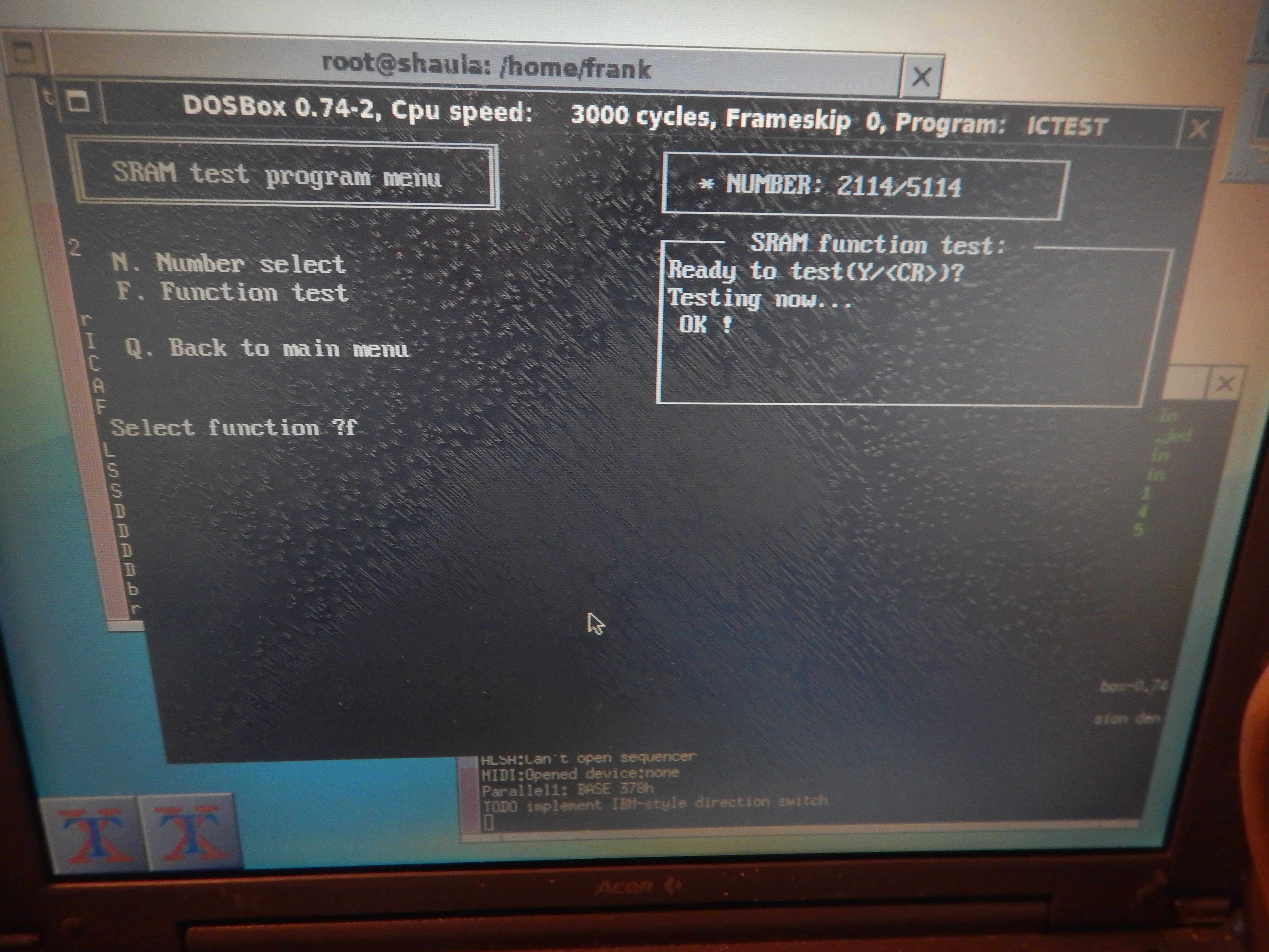
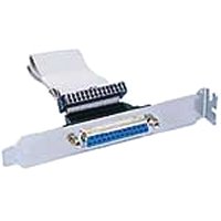
Connecting the Hilo ALL-03 to the parallel port of the
PC - courtesy Nicola (Germany)
- patches and configuration files for dosbox version 0.74-2.
The original source is at https://sourceforge.net/projects/dosbox/files/dosbox/0.74-2/dosbox-0.74-2.tar.gz/download
derived the first patch, which implements parallel port passthrough, from
https://www.vogons.org/viewtopic.php?t=11979
In the second patch added code that redirects accesses to ports 0x200-202
(for LPT1), 0x210-212 (for LPT2) or 0x220-222 (for LPT3), to the interface
board described below, which sits between the PC parallel port and the ALL03
programmer. To the original HILO software running under dosbox, it looks like
a SAC card at one of the addresses above, and I have tested that it correctly
operates the programmer. It is also possible to operate the ALL07 programmer,
of course no hardware adapter needed. It is very nice that in both cases the
original unpatched software from HILO can be used.
The configuration file is what I use to enable the passthrough from the virtual
LPT1 under dosbox to the real parallel port (/dev/parport0) on the Linux PC.
Note that I use this under Linux and never tested it under Windows.
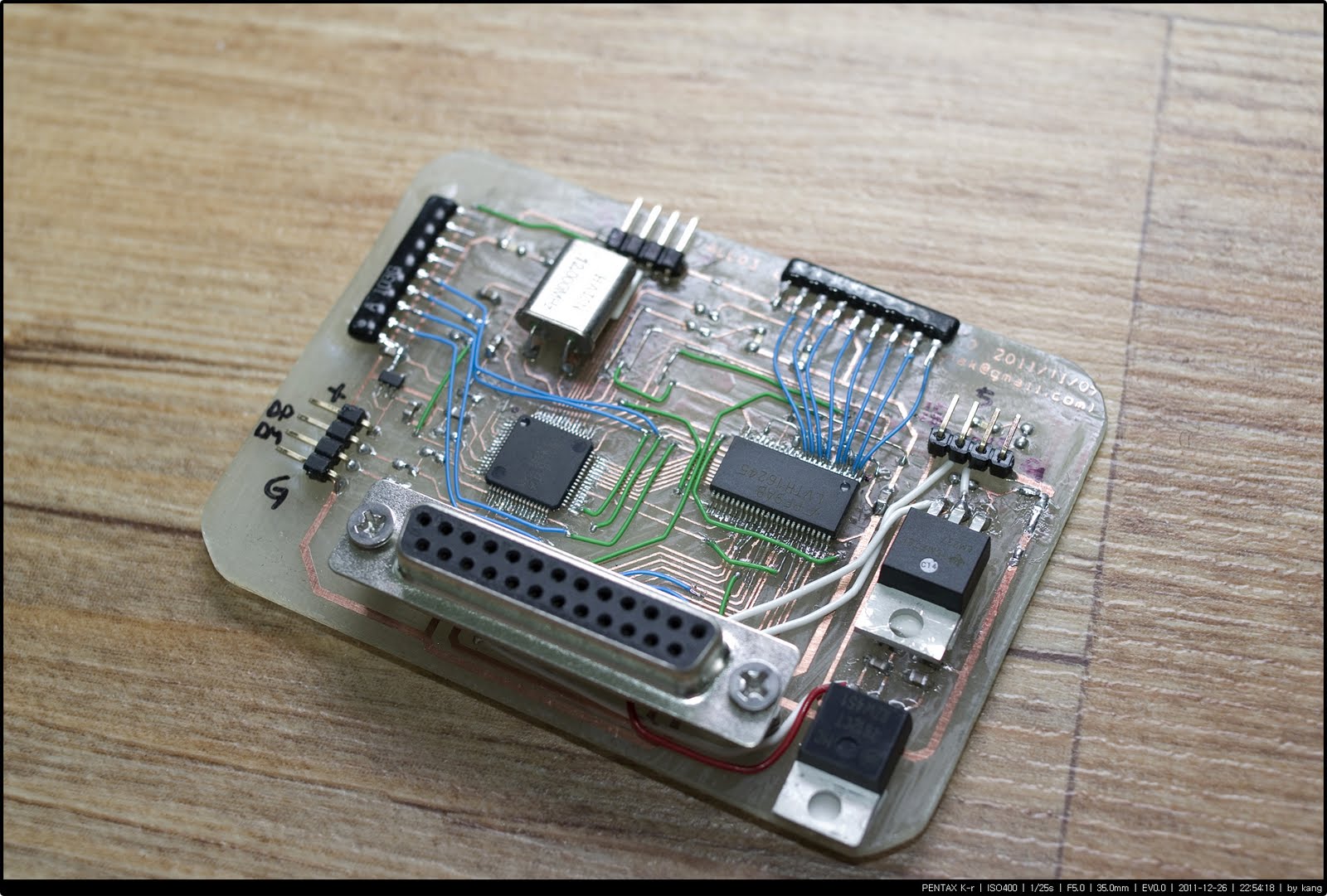
- PCB schematic, bom and design files, including CPLD source
and programming file, for a parallel port to ALL03 interface board. This is
powered by a 2A 12V wall wart and generates the +5V and -12V supplies for
the ALL03. I also included STL
files for a 3d printed enclosure.
Note that the transistor used for the -12V converter is an
old one from a junk box because I found after I milled the PCB that I ran
out of the BD138 I put in the schematic. It won't make any difference to the
operation.
Note that the holes of the barrel jack have been manually changed
because the PCB has been milled with a CNC router and it is a real hassle
to do noncircular holes, particularly if they are thin and long.
dosbox is very easy to use. After patching, compiling and installing
it, just put the original HILO ALL03 programs in a folder on the Linux computer
(I use ~/dosbox) and the configuration file I attached at ~/.dosbox/dosbox-0.74-2.conf
(note the dot at the beginning of the folder). You will note that at the end
of the configuration file there is an autoexec MOUNT line, this makes the
dosbox folder with the HILO programs become the C: drive.
> [autoexec]
> # Lines in this section will be run at startup.
> # You can put your MOUNT lines here.
> MOUNT c ~/dosbox
Then run dosbox. You will get a prompt on the Z: drive. Just
change to C: and run ACCESS. That's all.
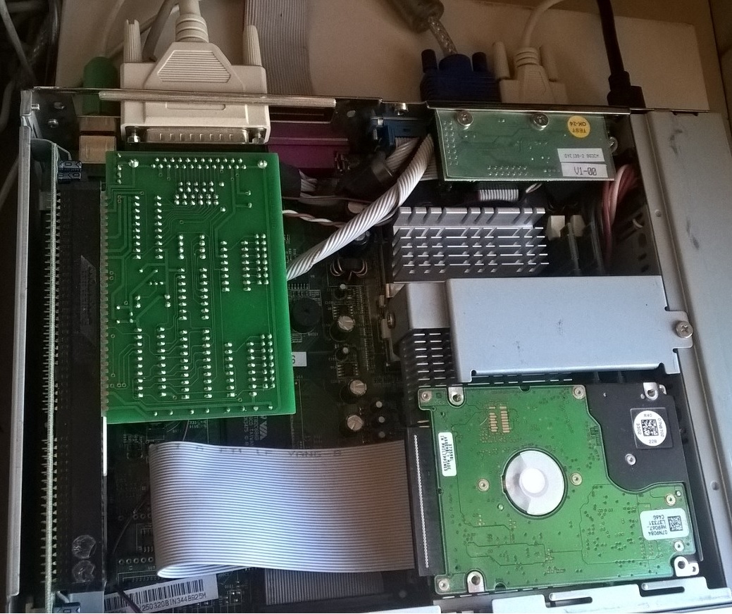
Frank (Italy) has done a All03 parallel interface with a current
production Atmel ATF1502 cpld
I know it's been a long time. but my work has consumed me all.
so many trips. and be face-to-face in high season. It hasn't let me continue
with the project until now.
I watched a lot of videos about reverse engineering PCBs.
and I learned something valuable.
I was doing everything wrong.
I should have started with the diagram first and not the PCB modeling,
now i am starting with the diagram like i should have from the beginning and
learned how to use kicad. which is much better than the easyeda.
So this time I'll do the last restart of the project to complete it and get
it up and running.
the preview that I have in the diagram. done in a couple of hours.(review
page 2)
Andreas(Germany) also made some drivers
for the ALL-03 (PROMA-3, compatible to the ALL03A, except
the OK button...) for the following CPUs (some are already present in the
original distribution) Microchip: PIC16C554, PIC16C557, PIC16C558,
PIC16C710, PIC16C71, PIC16C711, PIC16C715, PIC16F870, PIC16F871, PIC16F872,
PIC16F873, PIC16F873A, PIC16F874, PIC16F874A, PIC16F876, PIC16F876A, PIC16F877,
PIC16F877A, PIC16F83, PIC16F84, PIC16F84A, PIC16F627, PIC16F627A, PIC16F628,
PIC16F628A, PIC16F648A ATMEL: AT89C1051, AT89C2051, AT89C4051, AT89S8253
(some chip implementations might still be buggy though, as not all have been
tested...)
here
I send you all that I have/wrote for the ALL03/PROMA3 programmer. Please consider
it public domain (Archive ZIP - 229 Kb)
pic16.exe - commandline PIC programmer for the **parallel port** NOT
ALL03!!
ALL03.EXE Software to test the ALL-03 :test program does not make use of any
adapters, as there is no automatic checking. The user has select different
test steps and has to check every socket pin for the displayed voltages
based
on the good work done in proma3.zip, Christian(Germany)
has done a Variation of the included eep3.c.
The Dos application can be used to program the old Tesla mh74s571
Bipolar Prom.
The archive attached (mh74s571_all03.zip)
contains 3 files:
tbprom.c - Source
tbprom.exe - Dos executable
MAKEFILE - new Makefile for "Proma3 Project"
If you want to compile it yourself, you will have to unzip it into the
"Proma3 directory".
A new Makefile is included. The Dos executable is called tbprom.exe.
- bug fixed some code in EEP3.C (software
entry sequence for Flash devices was not correct, writing to address
0x555h and 0x2AAh instead of 0x5555h and 0x2AAAh)
- added other flash models (SST, still in production from Microchip)
in EEP3.C
- modified MPU6.C, now MPU7.C, to support AT89S51
- modified Makefile to add MPU7
- modified Timer.C to compile on newer compilers which adheres to newer
ANSI C++ standard (ex: Borland 3.0 or higher)
- modified FileFunc.c to avoid memory allocation problems with big files
and Borland C++ 3.0 (not sure about this, issues seems solved but not
sure)
here download the archive with the
new executables files for this update - sources compiled with TurboC and TASM
- (ZIP Archive - 81Kb)
MCT Programmer Modular Circuit Technology MOD-EMUP-A Programmer and Tester
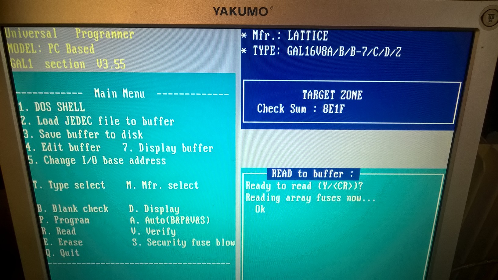
Here is the schematic of the SAC-201B
adapter card courtesy of Gonzalo Fernandez Val from SPAIN.
Please note the encircled letters A, B, C and D:
A: Appears "0" if the address is 2EX (X can be 0..F)
and AEN = 0
B: Appears "1" if the address is 2E0 or 2E1 and /IOW = 0 (write
2E0 signal)
C: Appears "0" if the address is 2E2 or 2E3 and /IOR = 0 and /IOW
= 1 (/read 2E2 signal)
D: Appears "0" if the address is 2E2 or 2E3 and /IOR = 1 and /IOW
= 0 (/write 2E2 signal)
Herafter the work of Jae-Gu Kang from South Korea.
Anyway, I have an ALL03 in my warehouse with dust, but my ALL03
is re-borned with USB interface.
Jae-Gu has developed a USB adapter card based TI's TUSB3210 USB client controller
for the ALL03 universal programmger, and it's tested with 32KB SRAM write/read
through USB connexion.
Jae-Gu has published schematics, device driver and test application
source for Windows XP OS on his blog.
But this ALL03 USB adapter card is under-development, so the program has no
device programming capability and it might has software bugs.
Jae-Gu will update my project continuously if I can get some time.
the Expro-60 is similar to the ALL-03 and the Expro-80 is similar
to the Expro-80 but there are some differences in each : The Expro-80 has
a 42-pin ZIF Socket while the Expro-80 has a 42-pin ZIF Socket
both requires 3 PAL16V8 and contents are different between Sunshine
Expro and hilo all-03 versions.
so schematics are slightly different,
for the moment I only have the Sunshine Expro-60 & Expro-80
schematics an PAL16V8 jedec files
if you have any details for the hilosystel All603 & All-03A
thank you to tel me
Hi!
If you can get a second hand Hilo Systems All03 device Programmer and tester
you will be able to program with no problem the AT89CX051.
You can use with it the free software compiled with DJGPP available on this
page.
Here
is the last Update (20030702 , 670Kb) of the software written by Fabio
Sturman (Italy). This Software includes software for programming
ATMEL AT89C1051, AT89C2051 and AT89C4051 ; MICROCHIP PIC16F83, PIC16F84 ,
PIC16C84 ; ATMEL AT90S8515, AT90S/LS2323, AT90S/LS2343, AT89S52, AT89C51,
AT89C52 , 27C512A, 27256 with the ALL03 / ALL03A programmer.
This software is compiled with DJGPP ( cf. http://www.delorie.com/djgpp/
) To compile it you need the following files (packages) : bnu, bsh, cpio,
diff, djdev, ed, fil, find, flx, gcc, glib, gpp, grep, gtxt, mak, sed, tar,
txt (look in the directory "x:\djgpp\manifest") .
In the directory "c:\djgpp" create this batch file and name it "djgpp.bat"
. Select the appropriate disk drive, select one of the shells uncommenting
one line at the end.
----begin file------
@echo off
set PATH=c:\djgpp\bin;c:\djgpp\gnu\emacs\bin;%PATH%
set DJGPP=c:\djgpp\djgpp.env
set PS1=\w \$
rem uncomment the following line if you want to use a bash shell
rem bash
rem uncomment the following line if you use win-nt4-2000-xp
rem cmd
rem uncommentthe following line if you use win-95-98-me
rem command
----end file--------
Expand the all03-x.zip into "c:\djgpp"
Start djgpp.bat from explorer, execute the command "cd all03/commandline"
and then the command "make". All the binaries and the libray will
be rebuild. If you want to modify only one module, change the source for the
module, save it and then execute "make" from the modules's directory
here
is the good work from Fabio Sturman (Italy) that is a new software
for the ALL-03 /ALL-03A device programmer which allow to program new devices
This new version allow you to program the 89c52 and 90s8515 microcontrollers.
The program is still runing under MS-DOS. The implementation of a Windows driver
for the SAC-201 board would be perhaps to hard for timing reasons. (Shift-Click
to Download :218 Kb)
here
is the archive of the expro60 Sunshine universal devices programmer which may
be very similar to the Hilosystems all03. This archive includes the sources
(equations) for the 3 PAL16R4 included in the expro60 named as follow : U5,
U33, U35. and also diagram for the expro60. (Shift-Click to Download :780 Kb) exp_u5.eqn (equations) , exp_u5.jed
(jedec file)
this is expro60 programmer board(Motherboards) of the CHIPS (PALCE16V8H U5).
exp_u33.eqn (equations), exp_u33.jed
(jedec file)
this is expro60 programmer board(Motherboards) of the CHIPS (PALCE16V8H U33).
exp_u35.eqn (equations), exp_u35.jed
(jedec file)
this is expro60 programmer board(Motherboards) of the CHIPS (PALCE16V8H U35).
Sheet 1 of 8 (EXPRO-60 INTERFACE PC)
Sheet 2 of 8 (EXPRO-60 SUB-BOARD PART I
ALIM)
Sheet 3 of 8 (EXPRO-60 SUB-BOARD PART II
ADRESS)
Sheet 4 of 8 (EXPRO-60 SUB-BOARD PART III
LOGIC)
Sheet 5 of 8 (EXPRO-60 UP-BOARD PART I LATCH)
Sheet 6 of 8 (EXPRO-60 UP-BOARD PART II)
Sheet 7 of 8 (EXPRO-60 UP-BOARD PART III)
Sheet 8 of 8 (EXPRO-60 UP-BOARD PART IV)
here you will find the same information but
for the expro80 including diagrams of the EXPRO80 and diagram and information
to build a LPT1 parallel Port interface for the programmer.
LINK-P1 parallel adapter for the EXPRO60-80 (ALL03 also ?) to use with the release
of the Expro60-80 dated 22 August 1996.
Use a standalone power power supply 220V -> +5,+12,-12. to power the programmer.
power ratings for a hilo all-03
Power: 5V - max. 0,5A (stand by) / max. 0,8A (aktiv)
12V - max. 0,3A (stand by) / max. 1,5A (aktiv)
-12V - max. 0,1A (aktiv)
Size: 262 mm x 142 mm x 45 mm
Power_100 User's Manualit includes Sunshine Expro-60, and Expro-80
User's Manual (PDF File 4.59Mb- 86 Pages)
Device driver for Win NT/2K/XP written by Hubert Sack
(Germany) - Works only with patched software of the ALL03 or EXPRO
60/80 devices programmers & testers : (available under the terms of the
Gnu Public License GPL)
Here Download the
Driver Expro.sys in order to use an Hilosystems ALL03 / ALL03A
or Sunshine Expro60 /80 with Windows XP/2000/NT Operating System.
(Shift-Click to download - 1.09MB)
See how to install the driver with Windows XP Operating
system through those shortcuts, and to verify the driver is already installed:
Download file PROG.DEV
from the Elektronikladen site. prog.dev is useful only if you use the all-03
software
To install the driver just copy EXPRO.SYS to the SYSTEMROOT\system32\drivers
folder and run INSTALLDRIVER. It installs the driver sets the startmode to
AUTOMATIC and starts the driver, so there is no need to restart the PC.
after installing the driver
it should appear "EXPRO-60/80" in the not plug and play drivers in
the peripherals manager
The black windows is because "INSTALLDRIVER" is a console application.
It
only do a few actions and exits (see the DELPHI project source
INSTALLDRIVER.DPR).
You can check that the driver is running in the control panel (see the
screencopy "DRIVER.JPG" how to find the information)
You can check it by a second way:
Open a console window ("CMD.EXE") and type NET STOP EXPRO
You must get a message that the service is stopped
After typing NET START EXPRO you must get the message that the service is
startet
keep address 2D0 (it is the address that I use with my SAC-201 ISA Card)
The ports 2E0 and 2F0 are
not supported by the driver because they may cause a dangerous conflict with
an existing COM3/4
A "file" (it's the symbolic link to the driver) \\.\EXPRO
must be opened in the program, which wants to do I/O on the ports. Therefore
only the patched programs in the attachment will work. That's
because the I/O permission map at the end of the TSS-descriptor is modified
by opening the driver. It's exactly the same way GIVEIO.SYS
does, but not for the 64K I/O hole , because the keyboard, mouse etc. must be
handled by NT/2K/XP like before.
With that "trick" the access to the port it as fast as under DOS because
IOPL does not matter, there is NO interception. The ports 2E0
and 2F0 arenot supported by the driver because they may
cause a dangerous conflict with an existing COM3/4. The control to the Kernel
is fully bypassed!
To install the driver just copy EXPRO.SYS to the
SYSTEMROOT\system32\drivers folder and run INSTALLDRIVER. It installs
the driver sets the startmode to
AUTOMATIC and starts the driver, so there is no need to restart the PC, but
please if it doesn't work first, reboot your computer then test it again.
A short description what the driver does (you can find it in the
internet if you search for GIVEIO.SYS
from Dale Roberts, the driver uses exacly the same "trick"):
Every task (in NT/2K/XP it's called PROCESS) have it's own TASK
STATE SEGMENT descriptor. The TSS
register holds the descriptor. You can see the structure of a TASK STATE
SEGMENT descriptor in the pictures here. Within the TSS
structure is an offset-field which points to a bitmap. This bitmap is the I/O
permission map. A "0" (bit, not byte !) allows the process
to access the port. For each address there is a bit, so 64kbits for the full
I/O address room is needed (8192 * 8 = 65536 = 64k). That's the reason why 2000h
bytes of non cacheble memory is allocated by the driver. The bits of the addresses
used for port I/O by EXPRO60/80 or ALL03 are cleared, all the
other ones are set to "1".
The application only must open the "file". The kernel calls the "open"
function of the driver.
It's executed within the context of the application process, but which CPL (current
privileg level) of 0 (it's the highest). So the driver is able to "adjust"
the I/O permission map of the task (e.g. process) to it's needs. Till now the
application can do direct I/O calls to the port. That's all; but it's sounds
easier than it really is: To reference a new I/O permission map you must call
two undocumented operating system calls.
The patch program does a very simple
thing: it adds the necessary code at the end of the original program image and
adjusts the header. So after loading the additional code is executed first,
which opens the driver to support the I/O permission for the process. There
are only two DOS calls used: Open file and Close file. (Shift-Click to download
- 8 KB)
To assemble the driver you must use the MASM32.
It's free of charge and can be downloaded for the intel
web site.
The install program for the driver is compiled via Borland Delphi 3.
The patch program is compiled by using Borland Pascal 7, but it can be compiled
under Turbo Pascal 6, too. Only one line must be changed: FUNCTION uppercase (CONST instr: STRING):STRING;
must be changed to: FUNCTION uppercase (VAR instr: STRING):STRING;
Borland Pascal 7 allows "CONST" parameters, the resulting code
is the same as using "VAR", but the compiler rejects all write
references to the parameter because it's declared as read only (constant).
The main control unit is on the adapter card (SAC-201).
There are two 8-bit I/O registers on the SAC-201 that are able
to control all I/O devices on the ALL-03 main module.
Register name I/O address
IDPORT base address+0
DATAPORT base address+2
The base address is the I/O address of the SAC-201 as defined by DIP switches
1 and 2. These switches allow a choice of 16 possible base addresses from 200h
to 2f0h (default is 2e0).
Every device on the ALL-03 main module can be controlled by writing its ID byte
to the IDPORT and then reading from or writing to the DATAPORT (the ID bytes
of the various devices will be shown below).
TABLE 2
Available control pins on test-socket:
1. VOPENID: 1, 5, 7, 9 to 32.
2. VHHENID: 9 to 32.
3. VCCENID: 40, 36, 34, 32, to 26, 9, 7, 5, 1.
4. VHHENCID: 32 to 28.
5. TTLID: all 40 pins can be defined as inputs or outputs.
Note: Devices that cannot use the previous pin definitions will require a special
purpose external adapter.
Example: We wish to write the value 7fh to #1 D/A device (ID = e5h).
Assembly Language
idport equ 2e0h
dataport equ 2e2h
mov ax,0e5h ;id number setting
mov dx,idport
out dx,al
jmp $+2 ;device recovery time
mov ax,7fh ;data writing
mov dx,dataport
out dx,al
jmp $+2 ;device recovery time
C Language
#define idport 0x02e0
#define dataport 0x02e2
Outp (idport, 0xe5) ;/* ID number setting */
Outp (dataport, 0x7f) ;/* data writing */
2. ALL-03 Device ID Mapping and Definition:
The following describes each 8-bit device and its associated ID bytes:
Power Source D/A Voltage Level Setting Device:
e5h : #1 D/A named VOPID, full scale is 25.5 volt (400 ma), resolution is 0.1
volt, minimum voltage setting is 10.2 volt
Example: Writing 255 to device e5h will set the #1 D/A to 25.5 volt, writing
102 to e5h will set the D/A to 10.2 volt.
e6h #2 D/A named VHHID, full scale is 15.3 volt (400 ma) resolution is 0.06
volt, minimum voltage setting is 5.1 volt
Example: Writing 255 to device e6h will set the #2 D/A to 15.3 volt, writing
85 to e6h will set the D/A to 5.1 volt.
e7h #3 D/A named VCCID, full scale is 10.2 volt (1A) resolution is 0.04 volt,
minimum voltage setting is 0 volt
Example: Writing 255 to device e7h will set the #2 D/A to 10.2 volt, writing
0 to e7h will set the D/A to 0 volt.
The levels of each power source can be set by the above three D/A devices. However,
additional devices are required to apply these voltages to the specified test-socket
pins.
Total 40 bits assigned to 40 pins on test-socket. LSB of e0h is assigned to
pin 1, and MSB of e4h is assigned to pin 40.
Each pin can be a TTL level input or output. Before inputting from the desired
pin, the user must output a high to that pin.
Example: After writing an ID byte (TTLID+i) to the IDPORT, one can then output
8 bits to the DATAPORT or input 8 bits from the DATAPORT.
Total 40 bits assigned to 40 pins on test-socket.
LSB of e8h is assigned to pin 1, and MSB of ech is assigned to pin 40.
Writing a high to a particular bit will apply the VOP source to the relevant
test-socket pin. Writing a low will disable the VOP source output to that pin.
Example: After writing ID byte VOPENID+1 to the IDPORT, and then outputting
8 bit data to the DATAPORT, VOP will be applied to the relevant test-socket
pins 9 through 16 via a 22 ohm current limiting resistor.
Note: 1. Test-socket pins 2,3,4,6,8 and pins 33 to 40 have no VOP control circuit,
so VOP cannot be output to these pins even though the relevant bit may have
been set to high.
2. VOP must not be applied to any pin for more than one hour.
Total 40 bits assigned to 40 pins on test-socket.
LSB of f0h is assigned to pin 1, and MSB of f4h is assigned to pin 40.
Writing a high to a particular bit will apply the VHH source to the relevant
test-socket pin. Writing a low will disable the VHH source output to that pin.
Example: After writing ID byte VHHENID+1 to the IDPORT, and then outputting
8 bit data to the DATAPORT, VHH will be applied to the relevant test-socket
pins 9 through 16 via a 22 ohm current limiting resistor.
Note: 1. Test-socket pins 1 to 8 and pins 33 to 40 have no VHH control circuit,
so VHH cannot be output to these pins
even though the relevant bit may have been set to high.
2. VHH must not be applied to any pin for more than one hour.
Writing a high to a particular bit will apply the VCC source to the relevant
test-socket pin. Writing a low will disable the VCC source output to that pin.
Example: After writing ID byte VCCENID+0 to the IDPORT, and then outputting
8 bit data to the DATAPORT, VCC will be directly applied to the relevant test-socket
pins 28 through 40.
VHH Level Output to Extra Pins Control Device:
The difference between these extra pins and the previously listed VHH pins is
that these extra pins have no 22 ohm current limiting resistor in series with
the VHH source. This is to permit some PAL VCC pins to be driven at high voltage
(over 12 volts) and high current.
f5h VHHENCID+0
f6h VHHENCID+1
Total 16 bits assigned to 16 pins on test-socket.
f5h b0 : not used f6h : not used now
bl : not used
b2 : not used
b3 : pin 32
b4 : pin 31
b5 : pin 30
b6 : pin 29
b7 : pin 28
Writing a high to a particular bit will apply the VHH source to the relevant
test-socket pin. Writing a low will disable the VHH source output to that pin.
Example: After writing ID byte VCCENCID+0 to the IDPORT, and then outputting
8 bit data to the DATAPORT, VHH will be directly applied to the relevant test-socket
pins 28 through 32.
"Other Pins" Control Device:
Some additional pins not previously specified will be listed here.
efh OTHERENID
Total 8 bits assigned to 9 pins on test-socket
efh b0 : low will set pin 20 to ground
high will set pin 11, 30 to ground
bl : hi will output VOP (source - 2.4) volt to pin 7.
low will disable output.
b2 : hi will output VOP (source - 2.4) volt to pin 25.
low will disable output.
b3 : high will output oscillator TTL level to pins 2 and 3.
Each pin is the inverse of the other.
low will disable output.
b4 : high will output oscillator TTL level to pins 18 and 19.
Each pin is the inverse of the other.
low will disable output.
b5 : high will select 4.432 mhz oscillator
low will select 2.216 mhz oscillator
b6 : not used
b7 : not used
Note: 1. All devices are reset to a low output at PC power on.
2. Voltage drops exist between the power sources and the test socket pins. These
voltage drop factors need to be included in the D/A power source level settings.
These voltage drops are:
VCC drop : 0.6 v, (= 15 steps)
VHH drop : 0.6 v, (= 10 steps)
VOP drop : 0.6 v, (= 6 steps)
Example: The following code sets the #1 D/A to 21 volt:
outp (IDPORT, VOPID)
outp (DATAPORT, 210+6)
3. Before inputting TTL levels, or outputting VOP, VHH, VCC voltages, the user
must output a high to the specified pin.
Otherwise, the relevant TTL input, or the specified supply voltage will be pulled
down to ground. This will result in damage to the affected supply.
4. In the version 1.0 of the Expro 40 we supply the source listing for TESTPRO.EXE.
TESTPRO source is a good sample file for the user who wishes to develop his
own software to program new devices.
here
download this version of testpro with source code (this is a self-extracting
archive) - Shift-Click to download (673Kb)
Source.gif scaled down to 800x600 pixels.
Right Click on your mouse and select View Image to see the original size (1371x1953
pixels)
If you have any comments or resources do not hesitate to contact
me by email at matthieu.benoit@free.fr
. Also If you have needs to get a SAC-201 Assembled and Fully tested board ,
Do not hesitate to contact me.


-1%2B.jpg)