 DC
Motor Controlled with PWM Resources Page - Ressources d'électrotechnique
de Puissance
DC
Motor Controlled with PWM Resources Page - Ressources d'électrotechnique
de Puissance 
![]()
DC
Motor Controlled with PWM Resources Page - Ressources d'électrotechnique
de Puissance
![]()
Here is a description of the driver circuit. It's based on the Microchip AN531
Application Note titled "Remote Positionner". The circuit given in the application
Note do not work , so this is a correction of the circuit:
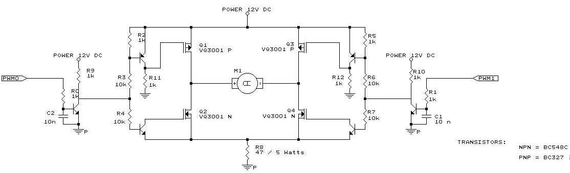
Here you can download the datasheet of the VQ3001 MOS Transistor Arrays
from SILICONIX. This chip is also manufactured by SUPERTEX.
![]() vq3001.pdf Shift-Click to download the datasheet (83 ko)
vq3001.pdf Shift-Click to download the datasheet (83 ko)
You can download here the AN531 application Note from Microchip of the
remote positionner with a PIC16C5X, and the source code.
![]() 00531e.pdf Shift-click to download the PDF file (443 ko)
00531e.pdf Shift-click to download the PDF file (443 ko)
![]() 00531.zip Shift-click to download the zip archive for the source code (53
ko)
00531.zip Shift-click to download the zip archive for the source code (53
ko)
To get the position feedback you can use a potentiometer and the serial ADC
ADC0832. This chip can be replaced by the LTC1098 from Linear
Technology.
A http://www.ancr.org/fichtech/action/ponthII/ EXEMPLE DE PONT EN H
http://mach.elec.free.fr/ Les machines électriques
H-Bridge Theory:
t's very desirable to use N-channel FETs for the high-side switches, but this means the gate-driver power supply must follow the FET's source, as it switches. You can make your own flying power supply to do this but it's more convenient to use a nice chip like the Intersil HIP4081A. http://www.intersil.com/data/FN/FN3/FN3659/FN3659.pdf If you're planning to leave the bridge continuously in one position for any length of time, the capacitor holding the flying gate-drive voltage in designs like the '4081 will discharge, so you'll need to have a floating supply anyway. There are chips with built-in high- side power-supply generators, e.g. ST's TD340, which looks nice, but I haven't used it, http://us.st.com/stonline/books/pdf/docs/7048.pdf
http://store.evparts.com/ EVParts - Electric golf car and cart parts and accessories
IRLxxxx mosfets are not conventional mosfets. They are characterized for logic-level gate drive. Their maximum gate voltage rating is also less than a conventional mosfet, so that >10V is possibly in excess of recommended limits. Read the spec, available free from IR http://irplus.irf.com/rqze6a4b/search/param-search/.
Motor Control Resources:
Has anyone here used this chip successfully? I'm designing a high frequency
PWM H-bridge using the HIP4080IAP MOSFET
driver (to provide +-3V output at 20 amps). After reading all the application
notes from Intersil they point out a "shoot through" situation can
occur when the the driver is first powered up. They provide a circuit to fix
this problem (see http://www.intersil.com/data/TB/TB3/TB321/TB321.pdf
)
It seems to me that this was a design fault in the driver because the fix they describe is shown at ends of application notes and is not included in the evaluation board. Their explanation of the issue is very brief and I was wondering if anyone who has used this chip before could recommend what to do about a power up circuit.
I have used the HIP4080A chip in several designs without any problem at all with powerup. Please notice that the TB321 was written for the '4080 and '4081 chips (old non-A versions, don't buy them, are even they still available?).
Of course the '4080A with its separate HI and LO inputs gives you the
capability to externally cause trouble, but that's
your issue! I would pay attention to the stuff in AN9404.
How are you planning to implement your H-bridge control?
I'm a really big fan of the 4080A and the 4081A, have used them to 2MHz, and have often recommended them here on s.e.d.
I have used it in the past and it worked well after sorting out some ground
bounce issues. The then Harris fae Ivars was very helpful in taming the beast.
I had to use a 33pf & 1 Ohm snubber from each output of H bridge to ground
and added 1 Ohm resistors in series with BHS & AHS lines to controller.
He had also suggested Toshiba Magnetics spike killer beads (AMO Beads?) on Source
Leads on top Fets & on Drain leads of bottom Fets. I didn't need to use
them though. Great part once
circuit is tamed but in the mean time plan on buying a tube for development
work. They arent very forgiving at high power levels.
I never occurred to me that there was a non-A version. If you and others have
not had problem with power up then I should be ok, since its the 4080A
which I have. The H bridge is basically a class D amplifier with an output voltage
range of +/- 3v at 20 amps max (output frequency requirement is below 500 Hz).
Switching freq. is 100 KHz using a CMOS 555 to generate triangle
wave that feeds the internal comparitor of the 4080A. I had used a 4080A
once in 10 KHz switching experimental circuit and found ringing in the bridge
is a real pain to keep under control. The ALS and BLS pins are only rated to
+/-2V (abs.
max.) with respect to Vss. I plan on using current sense resistors on the source
of two lower fets. Even a few nH of inductance here will cause the FET sources
to spike a few volts.
Since you have used these things to 2 MHz (above data sheet specs) I'm sure there's tricks to get them running reliably in high current designs. I may do as Jim Stockton suggested and buy a tube :). At AU$13 a pop from my own pocket it gets quite frustrating.
I'm interested how many circuit board layouts to you go through before getting it right ?
I'm surprised no-one's mentioned the ideal candidate, a washing machine motor. Pick one from an electronically controlled machine (nearly all are) and you will be able to run it off low voltage dc directly. Oh, and they're free. Ask anyone with a scrap machine. Mine will do 15,000 rpm as well, which is impressive for a commutator motor.
http://www.almico.com/speedfan.php Variateur de vitesse pour ventilateur
http://www.4qdtec.com/bridge.html Electronics Circuits Reference Archive H Bridge Motor control
http://www.maxonmotor.ch/ The leading Manufacturer of high precision Drives & systems
http://www.seidelservodrives.de/ Servomoteurs DBL/DBK
http://www.ostermann-net.de/electronic/ Liens intéressants concernant les moteurs
Verwende zum Umladen einen MOSFET-Treiber-IC wie MMH0026 = DS0026
= MC34151-52 (OnSemi, schwingt leicht), ICL7667 (Intersil),
LTC1693 (Linear), HIP4080-82A (Harris, nicht die nicht-A-Typen,
siehe TB321, aber lese AN9404), (siehe F.A.Q LinkList) Diese Chips
koennen das Gate mit 1-2.5A umladen, dann wird es schnell.... Dein t_raise wird
mit 1 Ohm eh schneller...
http://www.aaroncake.net/circuits/motorcon.htm Pulse Width Modulation DC Motor Control
http://www.maxonmotorusa.com/ Maxon
precision motors :they are not cheap, but I believe they can address needs speed,
stability, control, etc
Other Resources:
I've been monkeying around for the last week wondering how I'm going to drive
a high current load "high side" in an automotive application.
I am required to drive up to eight solenoids that can draw up to 25A continuously.
The solenoids are grounded to the vehicle chasis so that means I drive them
high side. Thermal limitations dictate that I have to drive these and consume
no more than 6W with the driver circuit. The driver circuit will be pulse width
modulated at 600Hz with duty
cycles ranging from 10% to 100%
First of all let me suggest some good readings in regard to high side gate drive
in general :
http://dsms.ajusd.org/~fritz/AN1.pdf
http://www.irf.com/technical-info/appnotes/an-937.pdf
Application Note AN-937 Gate Drive Characteristics and Requirements for
HEXFET Power MOSFETs Table of Contents
http://www.irf.com/technical-info/designtp/dt94-12.pdf
Those are some pretty big solenoids you are driving there. I'm curious what
you are working on. Could these soleniods be part of an electric power steering
or electric ABS braking system or something? Is the 600Hz
and 10-100% duty ratio requirements
set in stone or can you modify them slightly. It might make things easier if
you could get by with higher frequency PWM or 10%-99%
duty ratio instead of the full 100%.
If you use a full 100% duty ratio
that pretty much precludes the use of pulse transformers for isolating your
gate drive signal unless you use some fancy alternative schemes (ex: piggieback
your gate drive signal on a high frequency carry wave by amplitude modulating
a high frequency square wave into the primary of the tranformer, and then have
demodulating circuitry at the output). Actually though since this is such a
low frequency at such a convient voltage pulse transformers solutions may be
undesireably complex.
I suggest you build yourself a 555
or similar simple voltage doubler. Since the automobile voltage is 13.X volts
an unregulated double voltage should be plenty sufficient to fully enhance the
MOSFET (without destroying it provided you aren't using a logic level MOSFET).
Schematics for such a circuit should abound on the internet. It doesn't really
matter how you do it, but you will need a 13.X volts + 10V-20V source. The next
thing you will need will be a voltage level shifter/gate driver. Since you only
need a modest 1.67uS rise/fall time, the solution shouldn't need to be too complex.
An NPN/PNP totem pole solution should do the trick. The totem pole driver should
look something like this: http://dsms.ajusd.org/~fritz/TotemPoleDriver.pdf
Select small NPN and PNP transistors of sufficient size/voltage to provide your
target drive speed of less than 1.67uS. I suspect pretty much any selection
should work for this low switching speed. The MOSFET shown in the diagram is
needed to provide high speed voltage level shifting between your PWM signal
(presumably a 0V-5V or 0V-12V logic signal) and the transistor bases. This method
will invert your PWM signal. If this invert is undesireable you may need to
use another inverter somewhere in the circuit. Do not blindly substitute an
NPN transistor for the MOSFET without evaluating the consequences. Some NPN
transitors can have very long storage times which will (possibly) drastically
distort your gate drive signal.
The MOSFET such as a 2N7000 should
work just fine. For 0V-5V PWM signal swings you might use a small logic level
MOSFET (although in reality the 2N7000
will probably still work just fine since the threshold voltage is lower than
5V). Some PWM IC's such as the TL494 have (configureable) open collector outputs
already. With these you will not need the extra MOSFET, presuming that these
open collector outputs can handle 30+ volts. Pay attention and make sure you
don't accidentally introduce an unintended invert stage. Select an appropriate
resistor value. 1K Ohms might
be a good starting point.
Smaller values will probably shorten turn on time slightly, but will result
in higher dissipation/bigger load on the ~25V powersupply when the gate is driven
low. If your capacitive charge pump solution can't provide enough current, you
may need to build a simple inductor based boost converter. The output needn't
be too well regulated so this can simply be a 50% duty ratio oscillator (results
in 2X input voltage in regular boost topology) driving a small N-Ch. MOSFET.
Hang a large enough parasitic resistance on the output of the boost converter
such that the inductor current remains continuous (IE, continuous conduction
mode) throught the cycle and you will only end up with 2X the input voltage.
Short circuit protection may be inherent if you use a capacitive charge pump
voltage doubler circuit. If the capacitors are sufficiently small then the charge
pump will have a maximum output current before the output voltage will rapidly
fall (ideally). Overvoltage protection could probably be implemented with a
strategically placed zener diode. I have looked into paralleling multiple P-Channel
FETs to achieve this goal.
------
Problem is that this solution is pricey. Target cost for the driver circuit
is under $3. I am now looking into using a beefy D^2PAK N-channel FET
(Infineon SPB100N04S2)
with a Rdson at 140 degree C of 10mOhm or less.These parts do exist and I can
get them in volume for around $2.00.
------
The above suggested circuitry should fall well within the $3 figure. My question
is how you plan to get ~4-6W of dissipation in a D^2 PAK. Although the
D^2 PAK itself is capable of extremely high dissipation regular surface
mount situations will not be able to adequately dissipate 4-6W that you will
likely generate. That is a really nice part by the way. I might also suggest
you look into the IRFBA1404P,
IRFBA1405P MOSFETs
as possible alternatives since they are supposedly very rugged and specifically
designed for automotive applications. Digikey will sell the IRF1404
in 5K quantities for $2.664. Digikey isn't too well know for their cheapest
prices, you might be able to find better.
The problem with the N-channel solution is driving the gate of course. Total
gate charge on these large FETs is around 250nC. A collegue of mine showed me
a charge pump circuit (Motorola MC33198)
that will offer gate drive and circuit protection thermal, short, over voltage)
for around $0.80. The problem with this is that it cannot sink or source the
current needed to turn on the FET in 1.67uS. How did you come about the 250nC
figure? The datasheets for the non-logic level version I found suggest max.
160nC.
http://www.infineon.com/cmc_upload/documents/027/577/SPP_B100N04S2-04_1.pdf
The logic level version is rated at a maximum gate charge of 210nC, but at 10V
(is this standard?). The maximum gate charge at 5V is a fair amount less.
http://www.infineon.com/cmc_upload/documents/027/577/SPP_B100N04S2-04_1.pdf
Really though it seems like you are using overly large MOSFETs for this application.
If you could get by with a little bit more power dissipation you could use a
much smaller/cheaper MOSFET. If you save a dollar by going with a more modest
sized MOSFET you could buy quite a bit extra heatsink for that buck. Also considering
that this extra high side drive circuitry will
take space, you could probably have used that space instead for a bigger heatsink.
Can anyone think of an alternate high side gate pre-driver device that can sink/source
around 125mA, offer at a minimum short circuit protection, and cost under $1.00
in volumes of 100,000 a year? Either that or a FET that will suit my needs that
has a lower total gate charge? I know this is really reaching but I have deadlines
coming up...
The IRF1404 has max. gate charge of 200nC, but is available from digikey
in 10K quantities for $0.97156, cheaper than your Infineon part at $2.
http://www.irf.com/product-info/datasheets/data/irf1404.pdf
The IRF3706 might be a
possible choice if you are willing to more fully utilize (ex: push them to the
edge, but still within specs) your components. http://www.irf.com/product-info/datasheets/data/irf3706.pdf
This is a 20V device with 6mOhms typical, 8.5mOhms max (both at 10V GS). At
140 deg. C junction the multiplier is 1.5. So that means a typical resistance
of 9mOhms, 12.75 mOhms max. If you go by the typical figure it just barely makes
your limit. If you make your heatsink slightly bigger even the max figure might
be acceptable. Max gate charge is 35nC (at 4.5V GS). Available at DigiKey for
$0.69102 in 10K quantities. The device also features an extremely impressive
inverse diode reverse recovery time (if that is important to you). If you did
use this you would want to be careful on the gate since it is only rated for
+/- 12V. The breakdown voltage temperature coefficient is 0.021 V/K. This means
at -50 Celcius the minimum breakdown voltage would be 18.4V. It has an avalanche
current rating of 28A, so you shouldn't have to worry about it "latching
up" in avalanche mode if you don't fully snub the inductive spikes. The
forbidden fruit is tempting if you ask me.
-----
An alternate would be to give a current boost to the existing Motorola pre-driver. I've been toying with a push pull stage inserted between the gate driver output and the FET gate. However, this is getting tricky. It involves creating an alternate higher current charge pump used to feed the high side of the push pull network. I'd much rather go with a pre canned solution to save cost and board space. If you're up to the challenge please help. Anything you can offer would be greatly appreciated.
http://spazioweb.inwind.it/nferrarese/Elettronica/Progetti/Reg_vel/Reg_vel.htm
Variateur de Vitesse pour moteur 1000W
http://perso.club-internet.fr/ope/cybot_carte_moteurs.htm Carte de Commande Moteur orientée robotique "Cybot" avec contrôle prévu par PIC16F84
Last summer I was planning on building my robot with my own concept of an h-bridge... I figured you could just take an NPN and a PNP transistor and tie their bases and collectors together while having the emitter of the NPN on the ground rail and the emitter of the PNP on the +V rail.
Let's see if I can draw it:
            +V
             |
         B |/ E
      +----|  PNP
      |    |\ C
      |      |
IN --+      +---OUT
      |      |
      |  B |/ C
      +----|  NPN
           |\ E
             |
             GND
(Had to mark the pins with letters since I can't figure out how to put the arrows in...)
Of course, you'd have to do two of these for an h-bridge...
When I did this, it didn't work. I posted a message to an electronics forum
and learned that my whole understanding of transistors was flawed. Someone explained
to me why it wouldn't work, and it made total sense at the time. I don't understand
what the problem is anymore (something's getting shorted out somewhere, through
the base?).
Now, I'm looking in the Encyclopedia of Electronics Vol 5 for a circuit to make a -20V supply. One of the circuits in the book (page 456) uses an almost identical setup of the transistors as "power amplifiers". Except the emitter is switched with the collector, and the transistors are switched:
             +V
             |
         B |/ C
      +----|  NPN
      |    |\ E
      |      |
IN --+      +---OUT
      |      |
      |  B |/ E
      +----|  PNP
           |\ C
             |
             GND
Help! I'm so confused! First of all, I thought that setup is bad, because of this shorting problem (which I can't remember exactly what this problem is...). Second of all, the Collectors are tied to the rails?! Maybe I'm confused about the symbols... Isn't the following correct?
 NPN        PNP
  B          B
  |          |
-----      -----
  /\        ^\
v   \      /   \
E    C    E     C
Are these special transistors made to work like this? BC639 and BC640. If not, why couldn't one just use two of this setup as an h-bridge instead of using 6 transistors in the common setup?
--------------
The problem is that both transistors are being switched hard on by the current
from the other base. Maximum voltage between base and emitter is about B 0.9V
> E for a PNP and B 0.9V < E for an NPN. With these B-E voltages both
transistor
will be turned hard on. ie in saturation.
So in the diagram above the lowest you will ever get the B of the top transistor (before something blows !) is +V - 0.8 volts. The highest you will ever get the base of the bottom transistor is GND + 0.8 volts. With the 2 tied together something somewhere has got to give. Usually one of the transistors.
--------------
There is nothing wrong with this circuit, if the total supply voltage is about a volt. It would then turn the top transistor when the drive signal was pulled down near the negative rail, and would turn the bottom transistor on when the input pulled up to near the top rail. But for supply voltages greater than 1.2 volts, the two base emitter diodes form a short across the supply, and those base currents turn on both transistors at the same time, further shorting the supply. This basic circuit has to be modified so that a digital input (binary or trinary) can turn on only one base at a time, or neither. And that requires the connection between the two bases to be severed, and a more complicated interface built to convert the input level to one of two base current drives (or neither).
SIEMENS SLE4520 1kHz/ 20 kHz PWM-IC (discontinued)
* SIEMENS Application Note Pulse Width Modulator IC SLE4520 : 1/Principle of function, 2/technical feasibility of the system configuration consisting of SAB8051/SLE4520 combination, 3/Description of the functional blocks of the pulse width modulator (PWM) SLE4520 [on-chip oscillator, iinterface to the microcontroller, Divider control register, conversion of data word into pulse width, Dead time control register and dead time generation, interface to power stage, interlocking of the outputs], 4/ Application examples, 5/Initialization of the drive block, 6/ Table Access and output based on the SAB8051 example
* APPLICATION NOTES Elektor Electronics December 1987 : 3-Phase Power Converter for induction motors by K.Wetzel & W.Schumbrutki : A newly developed integrated pulse-width modulator and fast switching power FETs are the key components in a converter design which allows the good control characteristics of DC motors to be achieved with the more versatile 3-phase motor. (Advantages of converter-fed three phase motors, The three phase voltage supplied from the converter to the motor is not sinusoïdal, Pulse-width modulation, the SLE4520,. (Source Siemens Components XXI(1986) Nos. 1 and 2.
http://www.elnet.com/~gad/82C54PWM.pdf PWM Circuit that uses a 82C54 chip
PC Control of a DC motor :
(Electronics World April 2000)
This circuit, in conjunction with a PC, controls the speed and direction of rotation of a DC electric motor, via the PC's parallel port LPT1. It uses bridge connected complementary transistors with freewheeling diodes. Controlling the bridge are two 2SC1483 transistors which interface with the parallel port of the PC at address 378H. Data bits D0 and D1 , on pins 2 and 3 of the parallel port are used to drive the bridge circuit. Pin 25 of the parallel port is connected to the 0V ground of the bridge power supply. The simple QuickBasic program runs the DC motor at any speed in any direction . A data 0 on bit D0 and a 1 on D1 switch transistors TR1 and TR3 'on' resulting in current flow through the motor in one direction. A data 1 on bit D0 and a 0 on D1 switchs transistor TR2 and TR4 'on' resulting in current flow through the motor in the other direction, reversing the direction of rotation. The software controls the motor speed by pulse width modulation. If for example D0 is at logic 0 and hence Tr1 is 'on', current flow through the motor is controlled by switching on TR2 and TR3 alternatively. Setting the length of one FOR/NEXT loop, while adjusting the other to keep the sum constant, results in pulse width modulation of the motor current? With the QuickBasic program running on a P-1 166Mhz PC, a pulse-width modulation frequency of about 7kHz resulted. Speed and direction of rotation are controlled by the keys F1 and F2.
Article by M T Iqbal, Rawalpindi, Pakistan E4.
other Resources:
Question: I would like to build a H bridge for a DC motor. It's about 150 Volts less than 5 amps.I found L298 and L293 'ideal' however their voltage and current rattings are rather small. Therefore maybe I should build my own bridge.
I saw a bridge circuit at
http://www.armory.com/~rstevew/Public/Motors/H-Bridges/HBridge_NPN-PNP.gif
and tried to construct it.
I've used
TIP127 replacing TIP32
(PNP),
TIP122 replacing TIP31 (NPN),
2N3947 replacing 2N2222 (NPN small signal transistor)
Both inputs A & B where held 'low' and applied a 60V supply.
I found that the power transistors were heating up and the motor refuse to run
when either one of the input is signal 'high'.
Could it be that the resistor 33 ohms be the cause as I've change to a 2.2khms.
I would prefer to construct a FET bridge any comments and references on how
could I construct one?
Answer:
TIP127's are at max at 100v, so 150v would be too much
for them. Next, the internal resistance of the transistors will cause it to
heat up a lot. Thus you'd need heat sinks on them as well.
You should consider using PWM to keep the heat down, and also switch to CMOS
power FETS with low on resistances.
The MOSFETS are ideal for PWM methods. The idea of using PWM is to have the
transistors pass through the analog lenear phase rapidly so as to minimize the
heat buildup.
You can also parallel the FETS without problems too. Most of the FETS come with
built in Schottkey bypass diodes as well,
thus you shouldn't need external bypass protection diodes.
You should also consider using a H bridge controller IC such as the IR2104,
IR2184 etc..
(http://www.irf.com/product-info/datasheets/data/ir2104.pdf)
or IC's like the http://www.robot-power.com/
OSMC h bridge project.
Check out http://irf.com and their power MOSFETS, such as http://www.irf.com/whats-new/nr021029.html
or http://www.irf.com/product-info/datasheets/data/irf3415.pdf
or
http://ec.irf.com/ec/adirect/ir?cmd=compare&category=53&categoryName=HEXFET+Power+MOSFETs%2F%2FDiscrete+HEXFET+Power+MOSFET%2F%2FN-Channel%2F200V
Any of the International Rectifier IR2104 other driver chips have nice
schematic diagrams to follow for wireing up the FETS you choose. You can use
most any microcontroller to generate the PWM frequencies as well. Some guys
use 555 timer circuits to good effect as well, which is nice as you can
use a potentiometer to control the PWM duty cycle, thus slowing or speeding
up the motor.
You do realize that 150v DC is extremely dangerous. You are excercising extreme
care and caution with it?
DC grabs and holds onto you, AC throws you. Besides there is the explosion hazard
if your using batteries,
Using DC Motor as Dynamo
Depends on the motor. Brushed PM motor- no problem. Forward and reverse, so
you'll have to rectify the output.Of course, it will have to go fast enough
to produce the necessary voltage.Stepper, brushless etc. in principle maybe,
but practically not worth the effort.
48V Batteries:
Most proposed systems I've heard of use 36V batteries and 42V charging. Try
the manufacturers of 12V automotive batteries like Johnson Controls,
Exide, etc. Some Japanese cars sold in Japan are already using 42V
electrics, so Asian battery suppliers should probably be able to help as
well.
http://www.commlinx.info/Control.htm
Motor and general control schematics
http://voltaweb.elec.free.fr/robertg/motmono.html
liens moteurs mono
Triacs
A Triac is a bipolar Thyristor.
A thyristor switches on upon a trigger impulse and switches off when the current
becomes smaller than a holding current, usually assumed zero.
There are some made to switch off upon a negative pulse though.
The off-pulse current has to match the emitter current.
In DC, a thyristor can be used in a one time switch application. So a thyristor
can be used to short a power supply upon a fault
condition.
Silicon controlled rectifiers would be a better choice. If the supply is steady
dc (as in battery circuits) some form of
commutation (turn-off) will be required. If the supply is pulsating dc (as from
single-phase rectifiers) turn off will be automatic. You might be better off
with some type of transistor or relay load control.
The difficulty of using triacs and thyristors in DC circuits is turning them
off. Basically you have to divert all the current flowing
through the device for some micorseconds before it will go off and stay off.
That apart, they work fine.
>Actually in noisy environments, it's a bitch getting them to stay turned
on
>because they tend to commutate off so easily -- most industrial
>applications I know of use what is referred to as "hard gate picket
fence"
>firing -- a continuous stream of shaped trigger pulses for the duration
of
>the desired firing time.
Cite? I've used that method, but only for these reasons:
1) Less power required than with DC drive
2) It gets through pulse transformers for isolation
3) Either the drive is not syncronized with the zero crossings, OR there is an unpredictable amount of inductance in the circuit, so that it can't be assured that the load current will rise above the holding current near the zero crossing before the pulse ends.
low power PM DC motor speed control
Suggestion: Visit
http://library.kmitnb.ac.th/projects/ind/PNT/pnt0007e.html
http://user.aol.com/SAMINCO/ds032.htm
(needs to be scaled down)
http://www.4qd.co.uk/prod/1qd.html
http://www.nwlink.com/~kevinro/pcbchopper.htm
http://www.njr.co.jp/e08/sfe_03.htm
etc. for more info
![]()
http://fabrice.sincere.free.fr/qcm/qcm.php?nom=qcm_hacheur QCM Hacheur série
![]()
![]()
http://www.rougier-electro.fr/ fabricant français bagues_collecteurs electriques_charbons moteur_baguier_contacts tournants
![]()
http://educypedia.karadimov.info/electronics/circuitsmotorcontrol.htm
![]()
BLDC/PMSM Motor Controller
http://cache.freescale.com/files/microcontrollers/doc/user_guide/LVMCDBLDCPMSMUG.pdf 3-Phase BLDC/PMSM Low-Voltage Motor Control Drive
http://www.ti.com/tool/drv8301-rm48-kit Three Phase BLDC, PMSM Motor Kit with DRV8301, Encoder and RM48 Safety MCU
https://www.fairchildsemi.com/datasheets/FC/FCM8531.pdf MCU Embedded and Configurable 3-Phase PMSM / BLDC Motor Controller
http://www.microchip.com/pagehandler/en-us/technology/motorcontrol/motor-types/pmsm.html Permanent Magnet Synchronous Motor (PMSM)
![]()
http://www.zen13412.zen.co.uk/MCGManual.pdf
SEVCON MCM
![]()
Retour ŕ la page Circuits divers
![]() 15 juin, 2025
15 juin, 2025
Email :  matthieu.benoit@free.fr