
NXP Motorola (freescale) MC68705P3 mcu reader / copier / programmer
![]()
Note: Reading operates at 4 MHz Speed (Switch I2 in Position
0) in order to divide by 4 the read-out.
If one 68705P3 append to be hard to read then operates at 1MHz Speed.
The extraction of the program is done by consecutive verifications : This
task that can take up to 3 days is very reduced owing to a powerful algorithm.
Depending on the memory used in the microcontroller, it can takes from few
hours to a dozen of hours.
 |
MC68705P3S reader tool:
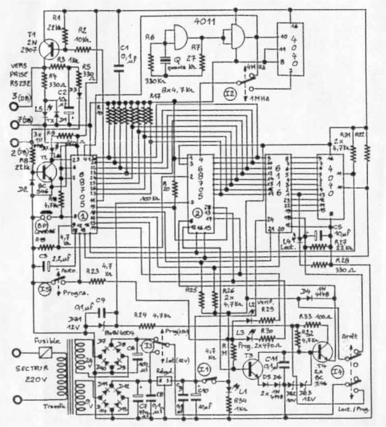
The diagram is given here :
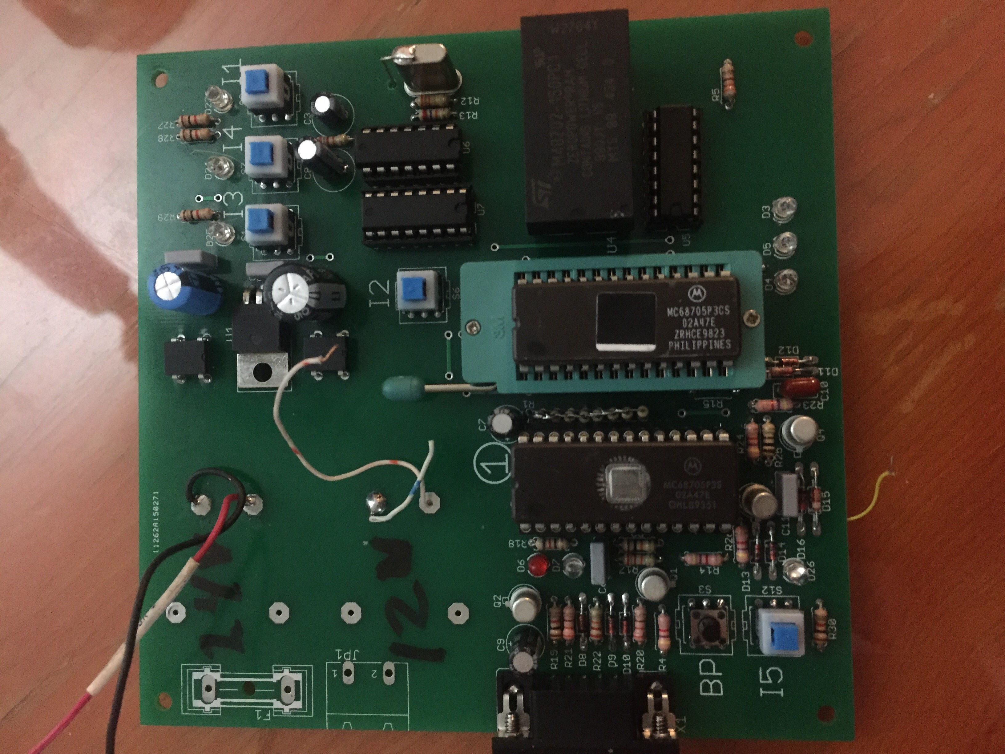
The SRAM 6116 can be replaced by the M48Z02 (or MK48Z02) Zeropowerram from ST , so that it can be read by a universal devices programmer.
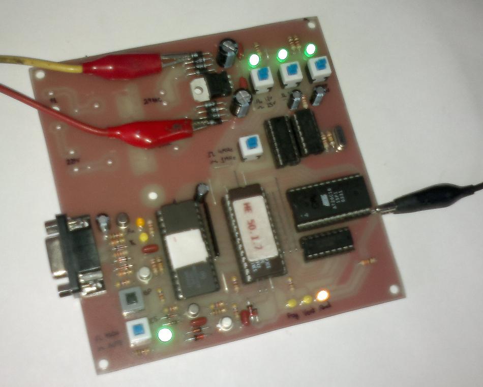
This tool is a dedicated reader / copier tool that allow to read out
the MC68705P3 mcu. |


![]()
![]() HOW-TO
USE:
HOW-TO
USE:
how-to-use (spanish)
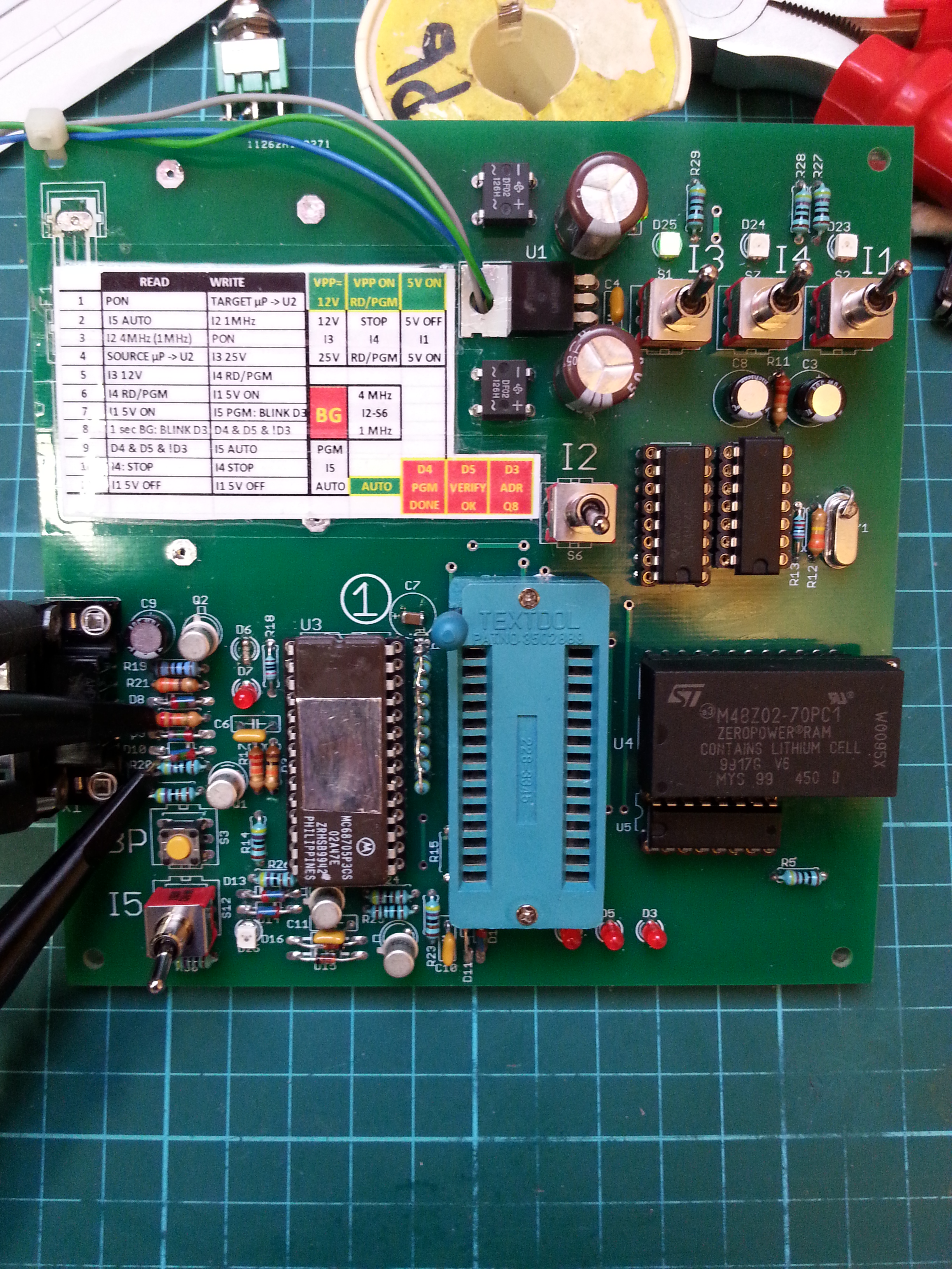
STANDALONE OPERATION:
READING OF THE MC68705P3:
Put Switch I5 on Position AUTO (0)
Put Switch I2 on position 4 MHz (0)
Plug the power
Put the 68705P3 containing the program to read in the Socket "2"
Put Switch I3 on position 12 Volts (0)
Put Switch I1 on position 5 Volts Operation (1) : Led L1 lights on
Put Switch I4 on Position Lect/Prog (1)
Press the key BP during a second then Led Led blinks every half seconds and
led L4 blinks very quickly. Reading is starting , extrcating the program in
the SRAM.
At the end of the reading Led L2 L3 stay lit but L4 is lit off
Put I4 switch in position Stop (0)
Put I1 in position Stop (0) Led L1, L2, L3 light off
Put away the MC68705P3 that has been read.
PROGRAMMING AN EMPTY MC68705P3
Fix the empty device on socket 2
Put switch I2 on position 1MHz (1)
Put Switch I3 on Position 25Volts (1)
Put switch I1 on Position Operation 5Volts (1) : Led L1 light on.
Put Switch I4 on position lect/Prog (1)
Put Switch I5 on Position Prog (1) : Led L4 blinks every 5 seconds approx. and
indicates that programming is in progress during 1mn 30s approx.
At the end of the programming, the led L3 lights on In the case the programm
has been transfered all right, Led L2 should light on 1 second after and indicates
the verification is OK Led L4 stops blinking.
Put Switch I5 on position Auto (0) : Led L2 & L3 light off
Put I4 on position Stop (0)
Put I1 on Position Stop (0) : Led L1 lights of Remove the programmed 68705P3.
![]()
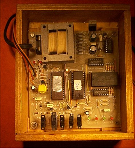
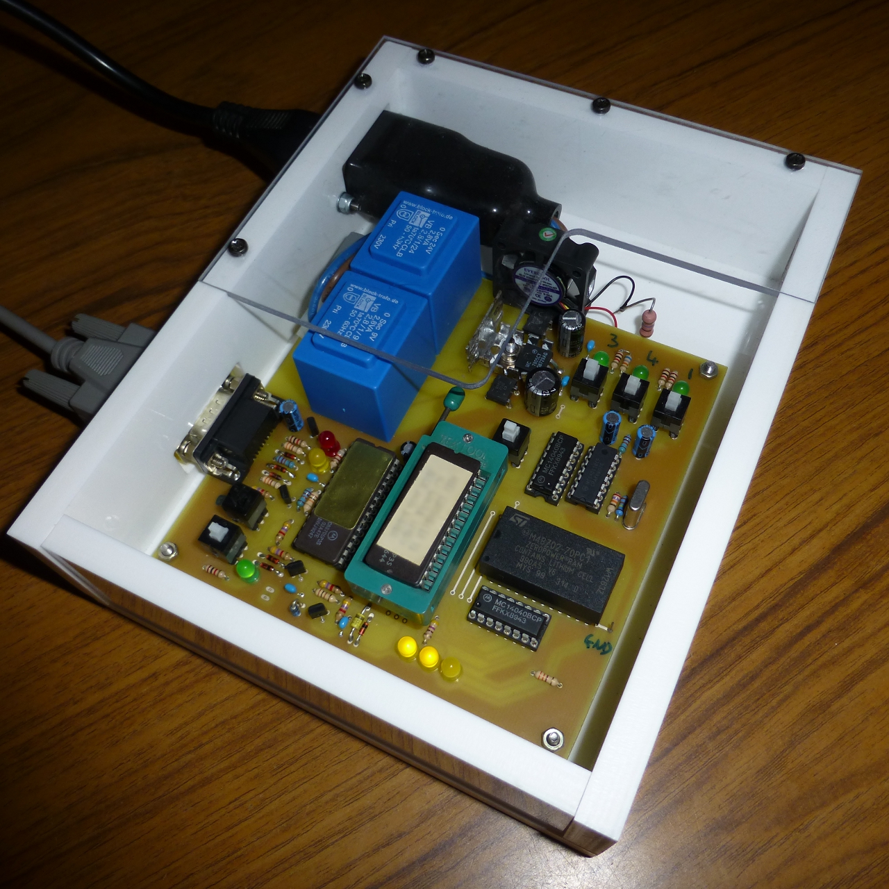
Power Supply : the power supply is done by a 5VA Transformer with 2 voltages 24 Volts and 9 Volts : the power does not exceed 5 Watts approx.
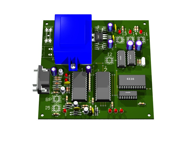
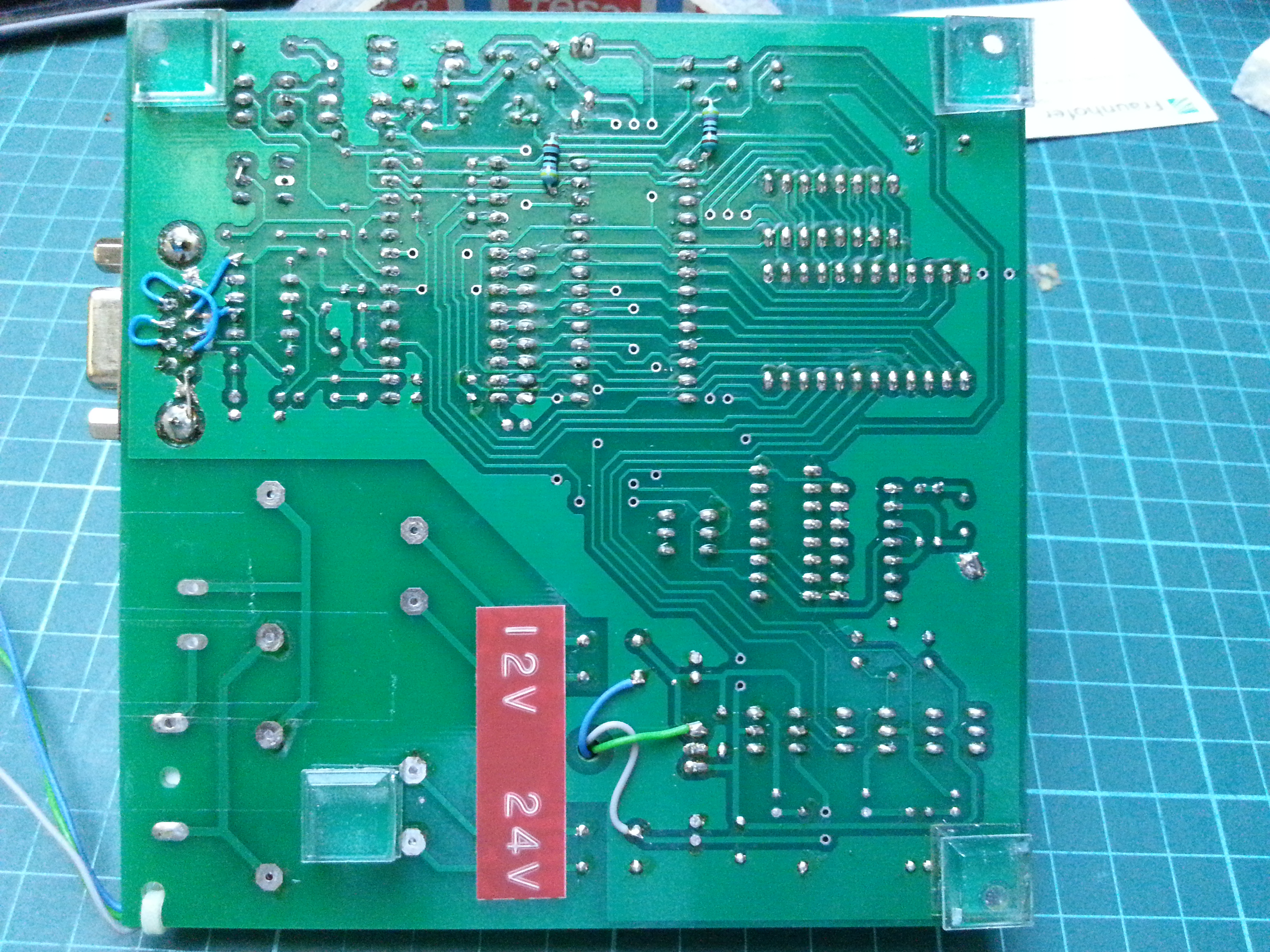
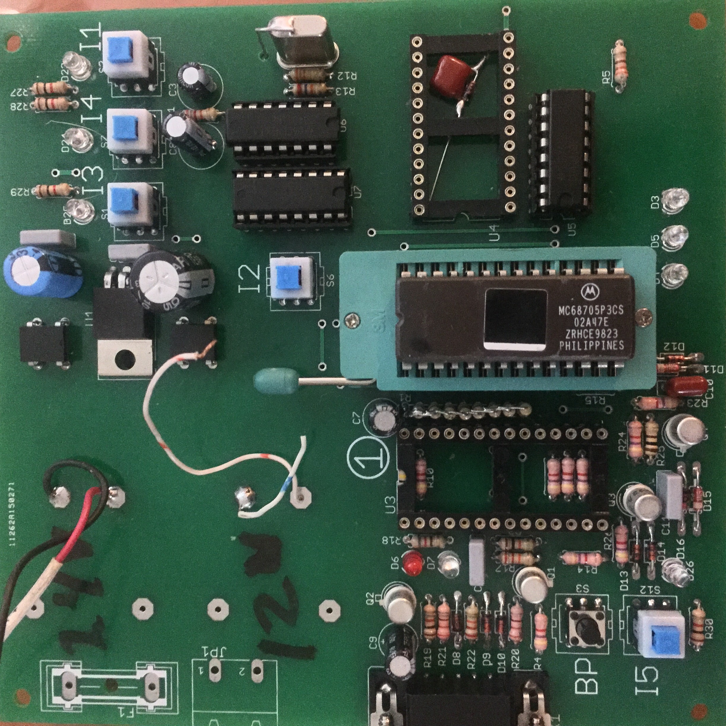
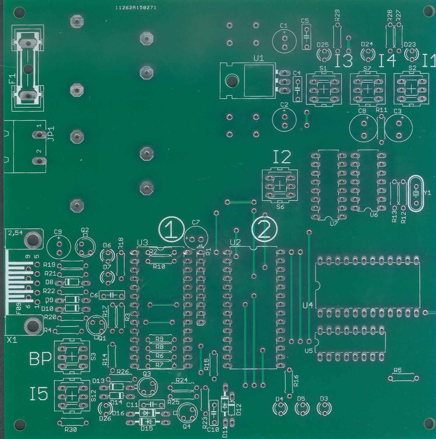
Components side:
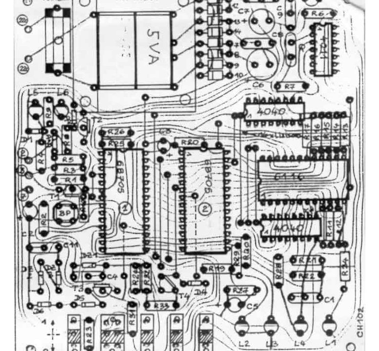
Diagram (schematic available here ![]() 68705p3.pdf (49 Kb) )
68705p3.pdf (49 Kb) )
![]() Diagram & Component (better scan version)
(269Kb)
Diagram & Component (better scan version)
(269Kb)
lect-p3
under MS-DOS before starting the program type the command MODE COM1: 19200,N,8,1 if connected to serial port COM1
on the manual of the kit it is not given
it is said :
press E to write RAM
press R to read RAM
press V to test if 68705p3 is empty
press P to program MC68705P3
press L to read P3
COM1/COM2 choice press O
press Q to Quit the program
led L5(TX) and L6(RX) display the operation on the computer
In order to work to the software lect-p3 you need the following connexion
Use de DB25 to DB9 adaptor if necessary.
DB25 -
(2) TX
(3) RX
(7) GND + Connect (4) & (5) each other ; Connect Also (6) , (8) & 20
each other. this allow the software to recognise if the programmer is plugged
or not.
so it means that on the SUB-D9 , pin 7-8 should be connected together and 6,1 and 4 should be connected together
1,4,6 should not be connected to pin 8, but pin8 should be connected to pin
7 on the SUBD-9 female connected to the serial port of the PC.
![]()
Components List
Transformer 5VA 2 outputs : 24 Volts and 9 Volts
Regulator 5 Volts L7805CV
Fuse 1.5A 250V and Fuse socket : fuse holder Littlefuse (Radiospares)
Programmed MC68705P3(1) [Checksum 18AF] 68705-1
Q Crystal 4MHz
2 x 28 pin Sockets , 1 x24 pin Socket ZIF Socket Optionnal
1 SRAM 6116 or ZEROPOWER RAM M48Z02-70PC1 (contains lithium cell 10 years) that
can be read by any Eprom programmer.
CMOS ICs : 74HC4040 x2, HEF4011 x1
5 SWITCHES ON-OFF 3 connexions
Transistors T2,T3,T4 : BC546
Transistor T1: 2N2907A
L1, L3, L5, L6 3mm Red Led
L2, L4 3mm Green Led
DZ2 BZX85C10 Zener
DZ1, DZ3 BZX85C12 Zener
1N4004 x 8 , 1N4148 x8
R33 :100 OHMS
R4, R5, R28 : 330 OHMS
R29, R30 470 OHMS
R9 : 820 OHMS
R3, R34 : 1KOHM
R10 TO R19, R19 - 21 TO 26 631 - 32 4K7OHMS
R2 10KOHMS
R1- R8- R27 22KOHMS
R7 : 27KOHMS
R20 : 100KOHMS
R6: 330KOHMS
C1-C4-C8-C9-C11 100 NF
C3 2.2µF/POL
C2-C5-C10 10µF/POL
C6 100µF/POL
C7 470µF/POL
Partlist exported from C:/EAGLE-7.1.0/projects/mc68705p3 reader.sch at 07/11/2015 08:28:24

Part Value    Device             Package      Description
C1   100u     CPOL-EUE2.5-7      E2,5-7       POLARIZED CAPACITOR, European symbol
C2   470u     CPOL-EUE2.5-7      E2,5-7       POLARIZED CAPACITOR, European symbol
C3   10u      CPOL-EUE3.5-8      E3,5-8       POLARIZED CAPACITOR, European symbol
C4   100n     C-EU050-025X075    C050-025X075 CAPACITOR, European symbol
C5   100n     C-EU050-025X075    C050-025X075 CAPACITOR, European symbol
C6   100n     C-EU050-025X075    C050-025X075 CAPACITOR, European symbol
C7   2u2      CPOL-EUE2.5-7      E2,5-7       POLARIZED CAPACITOR, European symbol
C8   10u      CPOL-EUE3.5-8      E3,5-8       POLARIZED CAPACITOR, European symbol
C9   10u      CPOL-EUE2.5-7      E2,5-7       POLARIZED CAPACITOR, European symbol
C10  100n     C-EU050-025X075    C050-025X075 CAPACITOR, European symbol
C11  100n     C-EU050-025X075    C050-025X075 CAPACITOR, European symbol
D1            DIODE-DO2-12       DO2-12       DIODE
D2            DIODE-DO2-12       DO2-12       DIODE
D3   YELLOW   LED3MM             LED3MM       LED
D4   YELLOW   LED3MM             LED3MM       LED
D5   YELLOW   LED3MM             LED3MM       LED
D6   RED      LED3MM             LED3MM       LED
D7   YELLOW   LED3MM             LED3MM       LED
D8   1N4148   DIODE-D-7.5        D-7.5        DIODE
D9   1N4148   DIODE-D-7.5        D-7.5        DIODE
D10  1N4148   DIODE-D-7.5        D-7.5        DIODE
D11  12V-0.4W ZENER-DIODEDO35Z10 DO35Z10      Z-Diode

D12  1N4148   DIODE-D-7.5        D-7.5        DIODE
D13  1N4148   DIODE-D-7.5        D-7.5        DIODE
D14  1N4148   DIODE-D-7.5        D-7.5        DIODE
D15  12V-0.4W ZENER-DIODEDO35Z10 DO35Z10      Z-Diode
D16  10V-0.4W ZENER-DIODEDO35Z10 DO35Z10      Z-Diode
D17           DIODE-DO2-12       DO2-12       DIODE
D18           DIODE-DO2-12       DO2-12       DIODE
D19           DIODE-DO2-12       DO2-12       DIODE
D20           DIODE-DO2-12       DO2-12       DIODE
D21           DIODE-DO2-12       DO2-12       DIODE
D22           DIODE-DO2-12       DO2-12       DIODE
D23  GREEN    LED3MM             LED3MM       LED
D24  GREEN    LED3MM             LED3MM       LED
D25  GREEN    LED3MM             LED3MM       LED
D26  GREEN    LED3MM             LED3MM       LED
F1   1.5A     GSH15              GSH15        FUSE HOLDER PTF75 or PTF76 with BS232
JP1  220V     GMSTBA2            GMSTBA2      PHOENIX
Q1   2N2907A  2N2907A            TO18         PNP Transistor
Q2   2N2222A  2N2222A            TO18         NPN Transistor
Q3   2N2222A  2N2222A            TO18         NPN Transistor
Q4   2N2222A  2N2222A            TO18         NPN Transistor
R1   4k7      G08R               SIL9         SIL RESISTOR
R2   100k     R-EU_0207/7        0207/7       RESISTOR, European symbol
R3   10k      R-EU_0207/7        0207/7       RESISTOR, European symbol
R4   4k7      R-EU_0207/7        0207/7       RESISTOR, European symbol
R5   330      R-EU_0207/7        0207/7       RESISTOR, European symbol
R6   4k7      R-EU_0207/7        0207/7       RESISTOR, European symbol
R7   4k7      R-EU_0207/7        0207/7       RESISTOR, European symbol
R8   4k7      R-EU_0207/7        0207/7       RESISTOR, European symbol
R9   4k7      R-EU_0207/7        0207/7       RESISTOR, European symbol
R10  4k7      R-EU_0207/7        0207/7       RESISTOR, European symbol
R11  22k      R-EU_0207/7        0207/7       RESISTOR, European symbol
R12  330k     R-EU_0207/7        0207/7       RESISTOR, European symbol
R13  27k      R-EU_0207/7        0207/7       RESISTOR, European symbol
R14  4k7      R-EU_0207/7        0207/7       RESISTOR, European symbol
R15  470      R-EU_0207/7        0207/7       RESISTOR, European symbol
R16  470      R-EU_0207/7        0207/7       RESISTOR, European symbol
R17  22k      R-EU_0207/7        0207/7       RESISTOR, European symbol
R18  820      R-EU_0207/7        0207/7       RESISTOR, European symbol
R19  1k       R-EU_0207/7        0207/7       RESISTOR, European symbol
R20  330      R-EU_0207/7        0207/7       RESISTOR, European symbol
R21  330      R-EU_0207/7        0207/7       RESISTOR, European symbol
R22  22k      R-EU_0207/7        0207/7       RESISTOR, European symbol
R23  4k7      R-EU_0207/7        0207/7       RESISTOR, European symbol
R24  4k7      R-EU_0207/7        0207/7       RESISTOR, European symbol
R25  100      R-EU_0207/7        0207/7       RESISTOR, European symbol
R26  4k7      R-EU_0207/7        0207/7       RESISTOR, European symbol
R27  1k       R-EU_0207/7        0207/7       RESISTOR, European symbol
R28  1k       R-EU_0207/7        0207/7       RESISTOR, European symbol
R29  1k       R-EU_0207/7        0207/7       RESISTOR, European symbol
R30  1k       R-EU_0207/7        0207/7       RESISTOR, European symbol
S1            PVA2S              PVA2R        ITT SWITCH
S2            PVA2S              PVA2R        ITT SWITCH
S3            PVA2R              PVA2R        ITT SWITCH
S6            PVA2S              PVA2R        ITT SWITCH
S7            PVA2S              PVA2R        ITT SWITCH
S12           PVA2S              PVA2R        ITT SWITCH
T1            EI48-2B            EI48-2B      TRANSFORMER
U1   7805T    7805T              TO220H       Positive VOLTAGE REGULATOR
U2            68705P3            DIL28        MICROCONTROLLER/MEMORY DEVICE
U3            68705P3            DIL28        MICROCONTROLLER/MEMORY DEVICE
U4   6116     6116P              DIL24-6      MEMORY
U5   4040N    4040N              DIL16        12-stage binary/ripple COUNTER
U6   4011N    4011N              DIL14        Quad 2-input NAND
U7   4040N    4040N              DIL16        12-stage binary/ripple COUNTER
X1            F09HPS             F09HP        SUB-D
Y1   4Mhz     CRYSTALHC49S       HC49/S       CRYSTAL
![]()
Assembling:

![]() MC68705P3 reader eagle schematic & PCB (RAR Archive -88 kb)
MC68705P3 reader eagle schematic & PCB (RAR Archive -88 kb)
MC68705P3 reader schematic (PDF- 35Kb)
Bill of Materials (.txt
- 8 Kb)
MC68705P3 reader (spanish) (RAR
Archive - 2kb)
You can use the circuit to write the 68705-1.bin
program. with this steps:
1. copy the 68705-1.bin in 6116 Eprom (AT28C16 for me)
2. I leave Socket 1 empty
3. Socket 2 with UC
4. pin 17 in socket 1 to GROUND
5. I1->5V, I3->25V, I4->Program.
6. pin 19 in socket 1 to +5V
WRITE begins!
![]()
![]() How
to read MC68705U3 EPROM by Peter Ihnat A method to read the EPROM contents
of a programmed MC68705U3/R3
How
to read MC68705U3 EPROM by Peter Ihnat A method to read the EPROM contents
of a programmed MC68705U3/R3
![]() MC68705P5 Bootstrap ROM
; blank.bin (2Kb-binary file This is a file
with all zeros) The Bootstrap ROM doesn't program zeros, it skips them
MC68705P5 Bootstrap ROM
; blank.bin (2Kb-binary file This is a file
with all zeros) The Bootstrap ROM doesn't program zeros, it skips them
![]()
Motorola MC68705P5 NUM Mode
read out
![]()
![]() Eagle BRD modified (.BRD compatible Eagle 7.1 - 164Kb) courtesy Tristan
Gallop (UK)
Eagle BRD modified (.BRD compatible Eagle 7.1 - 164Kb) courtesy Tristan
Gallop (UK)
![]() Gerber files archive MC68705P3 reader (ZIP Archive - 138Kb)
Gerber files archive MC68705P3 reader (ZIP Archive - 138Kb)
made the following changes based around the components I was able to obtain at the time...
1. Separate 24v and 9v 2,8VA transformers:
http://uk.rs-online.com/web/p/products/7320395/
http://uk.rs-online.com/web/p/products/7320370/
myrra 50/60Hz
2.8VA transformers
2. DF02 bridge rectifiers instead of single diodes:
http://uk.rs-online.com/web/p/products/6294914/
or DF08 bridge rectifiers https://www.stquentin-radio.com/index.php?page=info_produit&info=4925&color=9&id=0&act=0
3. Switch traces modified to suit the "Turbo" switches found in most older PC cases ;)
There are plenty of the push button switches on ebay, I searched for "pcb
latching push switch" and lots came up.
I think the ones you need for my PCB have the white button, not the blue but
I may be wrong! There is no information about the pin configuration.
https://www.ebay.com/itm/20PCS-Push-Button-Non-Latching-Momentary-Tactile-Switch-7x7mm-Blue-Button-6-Pin-/191674369075
I found a blue one at work and it seemed to be set correctly for the original PCB design.
4. 68k resistor added next to R29 to bleed the 24v capacitor when 230v is removed. The resistor is basically connected directly across C1
The rest of the board and component list is the same as the original design.
The toggle switches are digikey 450-2099-ND SWITCH TOGGLE DPDT 0.4VA 20V. very expensive.
https://www.digikey.fr/fr/products/detail/te-connectivity-alcoswitch-switches/TMD1T5B2M2RE/5125719
NOTE: these do NOT fit into the layout,You have to widen the holes on the PCB with a larger drill to make them fit
The 4 MHz quartz didn’t start up reliably, sometimes it ran at 8MHz. I drilled a small hole into the pcb besides the quartz and soldered a direct connection from the quartz’s can to GND (see photo). That assures reliable start-up at 4 MHz
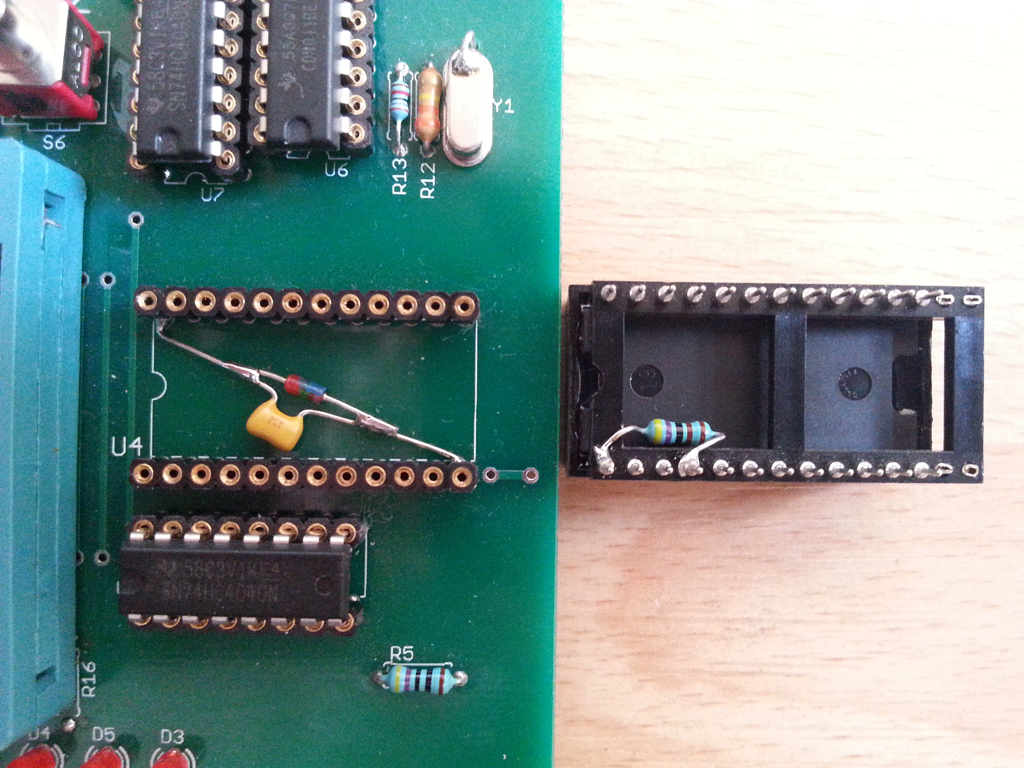
R15 and R16 collide with the textool socket, so I had to solder them on the underside of the PCB.
rework the connections on the RS232 plug, so I can use a 1:1 cable. However, I can’t get the software to work, although I was using a true DOS 6.22 computer
the zero-power RAM ST M48Z02 was plugged on an intermediate socket before plugging it into the PCB socket, because
to have some protection of the RAM’s pins from bending
need to solder a 4k7 resistor between pins 24 and 21 directly into the intermediate socket in order to protect the RAM from corrupting its contents when inserting and removing it from the PCB. Also, there is an extra 100nF capacitor and a 4148 diode (see picture) for the same reason
avoid mains transformers and connected the voltages from DC lab supply directly to the regulators.
![]()
![]()

M48Z02 replaced my a DS1220 with external lithium cell.


.jpg)
![]()

M48Z02-70PC1 RS 624-8488

M48Z02 Zeropower SRAM read with SMS Sprint Expert programmer

MC68705P3 programming with Hilo ALL-03 programmer and -68705/P3 adapter


![]()
If you need a PCB of the MC68705P3 Reader do not hesitate to contact me

(24/05/2026 1pcs pcb available)

![]()
Other Resources:
*******
If you look forward for other information about this MC68705P3 Reader, do not
hesitate to contact me by e-mail at: matthieu.benoit@free.fr
.
Si vous recherchez des informations pour ce lecteur de MC68705P3, vous pouvez me contacter par e-mail : matthieu.benoit@free.fr . De même si vous avez des informations sur ce programmateur, n'hésitez pas à contribuer à cette page.
![]() 24 mai, 2026
24 mai, 2026
 68705p3.pdf


 Retour au sommaire
 Retour
à la Page d'accueil
Retour
à la Page d'accueil matthieu.benoit@free.fr