![]() Motorola
(freescale) 68705, 6805, MC146805, HC05 microcontroller family
Motorola
(freescale) 68705, 6805, MC146805, HC05 microcontroller family
![]()
![]() How to read MC68705U3
EPROM by Peter Ihnat A method to read the EPROM contents of a programmed
MC68705U3/R3
How to read MC68705U3
EPROM by Peter Ihnat A method to read the EPROM contents of a programmed
MC68705U3/R3
![]() MC68705P3 Advance
information data sheet
MC68705P3 Advance
information data sheet
![]() MC68705P5 Advance information data
sheet
MC68705P5 Advance information data
sheet
![]() MC68705R-U Advance information data
sheet
MC68705R-U Advance information data
sheet
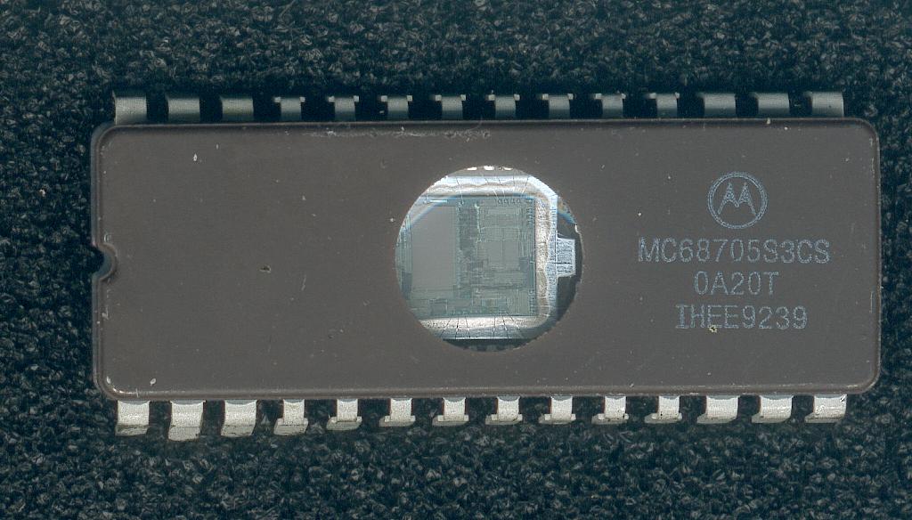
![]() MC68705S3 Advance
information data sheet
MC68705S3 Advance
information data sheet
![]() MC68705P5 Bootstrap ROM
; blank.bin (2Kb-binary file This is a file
with all zeros) The Bootstrap ROM doesn't program zeros, it skips them
MC68705P5 Bootstrap ROM
; blank.bin (2Kb-binary file This is a file
with all zeros) The Bootstrap ROM doesn't program zeros, it skips them
![]() source
code to view the bootstrap rom of the P3, U3, S3 by Peter Ihnat (Australia)
(PDF - 4 pages - 58Kb)
source
code to view the bootstrap rom of the P3, U3, S3 by Peter Ihnat (Australia)
(PDF - 4 pages - 58Kb)
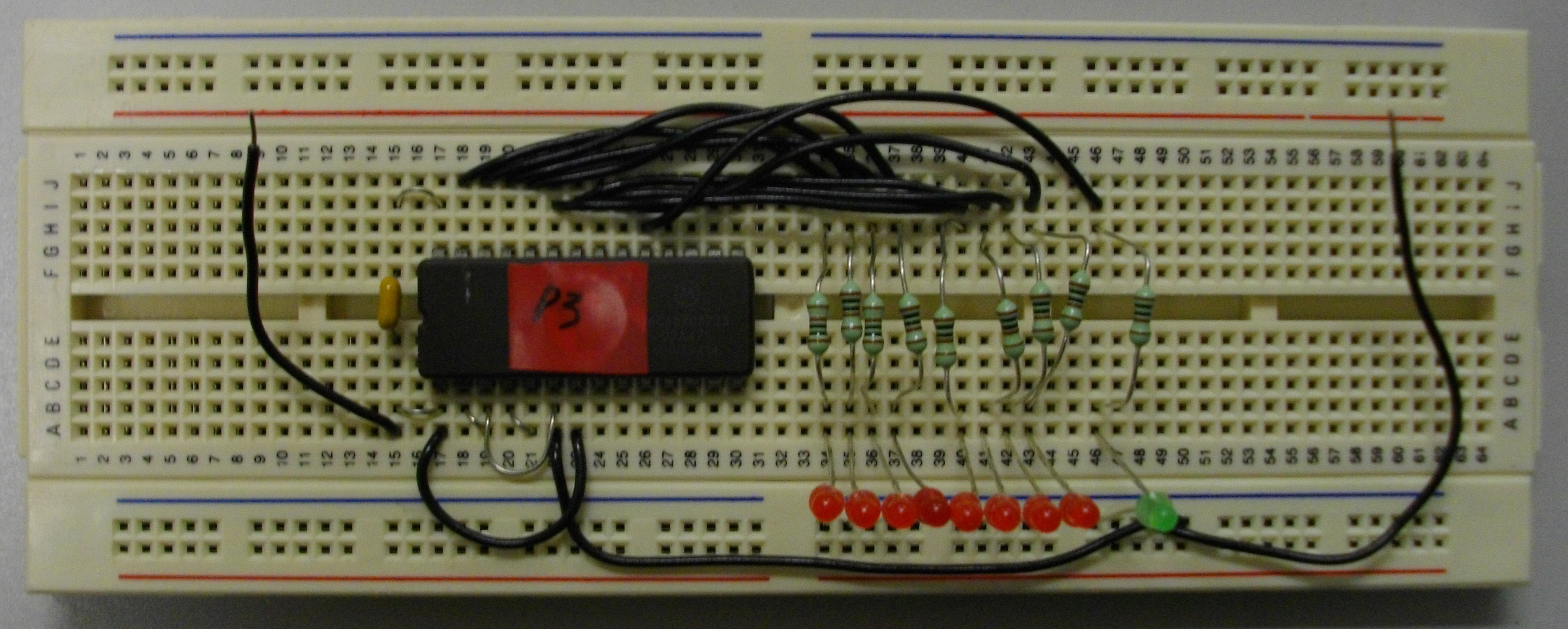
![]() dumpp3.asm | DUMPP3.BIN
(Binary - .BIN - 2kb)
dumpp3.asm | DUMPP3.BIN
(Binary - .BIN - 2kb)
![]() DumpP3.bin ( Binary- 2Kb) courtesy Peter
Ihnat (Australia)
DumpP3.bin ( Binary- 2Kb) courtesy Peter
Ihnat (Australia)
![]()
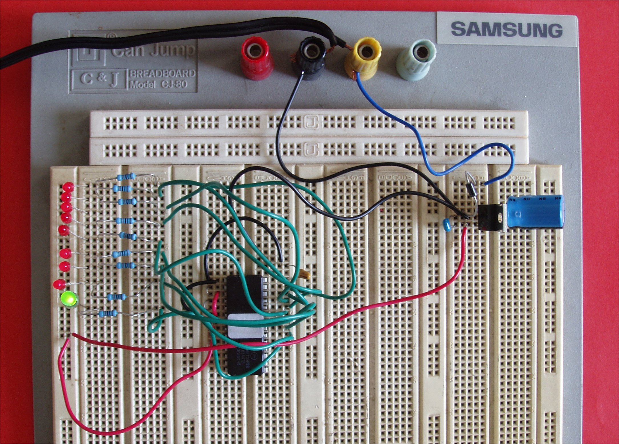
DumpS3.bin corrected (.Binary- 4Kb) code to view bootstrap rom of the MC68705S3
1K resistor between vcc & reset pin
data ready connected to pb0
source code of the bootstrap ROM of the MC68705S3 microcontroller (.LST)
![]() bootstrap ROM of the MC68705S3
(.BIN)
bootstrap ROM of the MC68705S3
(.BIN)
analysis source code bootstrap rom of the MC68705S3 (.LST)
![]()
https://www.americanradiohistory.com/Archive-Modern-Electronics/Computer-Craft-1993-10.pdf
Standalone MC68705 programmer by Edward Oscarson
A https://easyeda.com/barcsa/68705-fe6f53553ec44377879551cbc76fe0ab
MC68705U3/R3 programmer
https://dbhsarl.eu/pageperso/program.htm
MC68705P3 programmer
Astec ADIP26A05 DC/DC Converter can be replaced by http://www.icstation.com/sx1308-converter-step-adjustable-power-module-booster-converter-p-6016.html
https://www.nxp.com/docs/en/data-sheet/MC6805S2.pdf See page 130 programmer schematic - pinout MC68705S3 page 125
MC68705S3, MC68705P3,
MC68705U3/R3 programmer schematics (Documentation Motorola)
See AN857_REV2.PDF
and 6805_eprom_programming.pdf
MC68705S3 programmer:
The programmer that I used to program these MCU's : see page 130 of the datasheet
:
https://www.nxp.com/docs/en/data-sheet/MC6805S2.pdf
(that are the same circuit as you send me). To supply the +26V I used lab power
supply. What is important: +5V and +26V has to be supplied in the same exact
moment. Missing +5V with +26V present will probably fry the RESET/Vpp pin in
MCU (I damaged 2 MCU's before I realized that). Instead of 2732 i used either
27C256 or 27C512 (as I had these) with higher addr lines tied to GND.
![]()
![]() DL408D
Rev1 Motorola 8-bit MCU Application Manual 1992 (PDF- 726 pages - 40.69
Mb)
DL408D
Rev1 Motorola 8-bit MCU Application Manual 1992 (PDF- 726 pages - 40.69
Mb)
![]()
![]()
Motorola (freescale) MC68705P5
NUM Mode read out
hereafter an easier way to dump the ROM from 6805s and 68705s. I first got it working using the 6805’s NUM pin, then the same technique worked on an 68705, by setting PC0 to 7.5V to get into NUM:
http://www.seanriddle.com/mc6805p2.html Motorola MC6805P2
http://www.seanriddle.com/mc68705p5.html Motorola MC68705P5
hereafter the work from Sean Riddle:
he was able to dump the Milton MC6805P2 electronically using non-user mode. But oddly enough, he wasn't able to get it
to go into self-test, even though that's well documented.
he put the chip on a breadboard and gave it power, put a 1MHz clock on EXTAL, grounded XTAL, tied /RESET, /INT and TIMER high
and connected NUM to +5. He checked each port with an LA and noted that all PORT A bits were high, PORT B bits were toggling
(apparently) randomly, PORT C<3> was high and C<2:0> were toggling.
So he assumed PORT A and C<3> were inputs and the others were outputs. I figured opcodes would be fed into PORT A, so
he used 8 1K resistors to +5 and ground to set it to $9D, the opcode for NOP. I also tied C<3> high for the first test. He
captured PORT B and C<2:0> and was surprised to see an obviously repeated pattern every 16384 uS. Looking closer, there were
8 clocks between bytes being output, and 16384/8 = 2048, which corresponds to the 11-bit address space. Port C<2:0> outputs
bits 8-6 of the address bus, so it counts from 000 to 111 four times during a complete dump.
After searching for a while, He found the bytes that he had visually transcribed from the Milton die shot. HeI verified that all the electronic dumps I made were identical, then compared the electronic dumps to the visual dump, and found 4 more bit errors in my visual dump.
he was confused about where the dump was starting; each time it re-started at the same byte after reset, 1437 bytes in.
Then HeI realized that it was fetching the reset vector from $7FE, but was getting $9D9D from the resistors, which translated to $59D in the 11-bit address space. So it dumped from there to the end before wrapping around to $000.
he was expecting to have to feed the chip opcodes to dump the ROM contents, so he was surprised but happy that it turned out
there was a simpler way. It looks like in non-user mode that the chip fetches the byte from memory and puts in on PORT B,
then executes the opcode on PORT A. Since he had made it a NOP, it just kept fetching the next byte. I'm not sure if any of the other 6805 varieties will do the same, but maybe this will help.
he found out later that this also works on the 68705P5, if you use 7.5V on PC0 to enter NUM.
The data output to Port B is a byte of address info, a byte of memory, another byte of address info, and the same byte of memory. The address info is a permutation of the address bits.
This dumps everything in memory, not just the EPROM bytes. So you get the I/O ports, RAM and the bootloader code.
he also set the resistors to other opcodes to see what would happen. One of the opcodes I used was BRN, since it’s essentially a NOP. It also dumped ROM, but the number of bytes that it output on port B was different because it’s a 2-byte, 4-cycle opcode whereas NOP is 1-byte, 2-cycle.
![]()
RS-232 routines for MC68705 courtesy Steve Chandler
i2C bus routines for MC68705 courtesy Peter Jakacki (Australia)
![]()
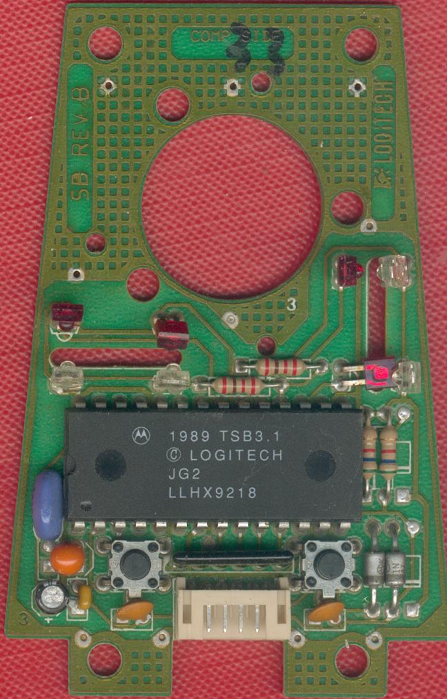
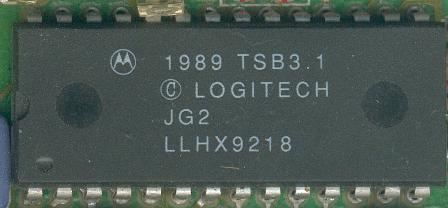
|
Motorola 1989 TSB3.1 (c) Logitech JG2 |
![]()

Serrure codée à 68705P3 (Article RADIO-PLANS n�574 /P.58-59) A simple project to test MC68705P3 programming : lockp3 project ( Electronique Radio-Plans n°574/P.58-59)
|
![]()
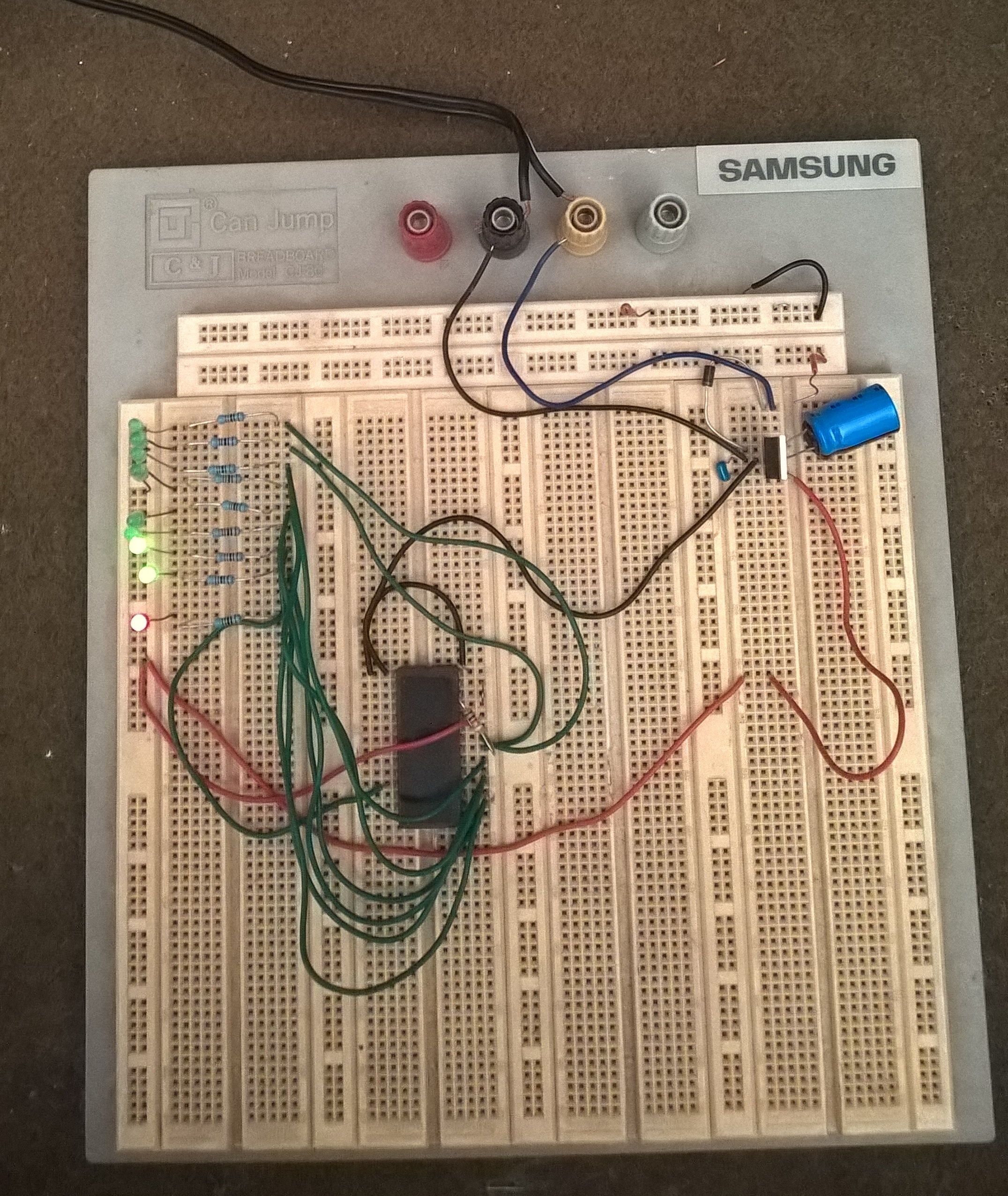
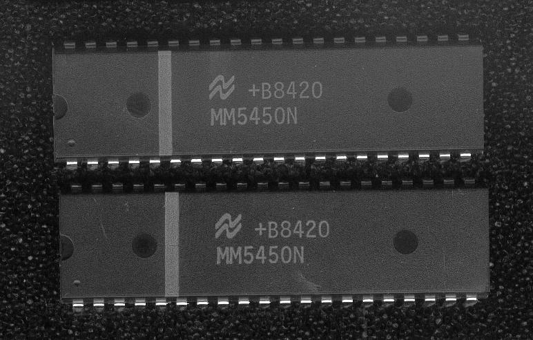
arrosage.src courtesy F.Boisard (France) MC68705R3 and MM5450 interfacing to control a 4 digit led display to display time and water metering
|
This application manages the automatic watering of a garden, with three watering
zones. |
![]()
Mecalogic MC68705 development tools A http://jean-michel.roux.pagesperso-orange.fr/mecalogic/ml68705dev.htm
https://forum.system-cfg.com/viewtopic.php?f=1&t=10752 MC68705P3 Mecalogic development tool
![]()
A Roger's
embedded microcontrollers 6805 68HC05 info page
A http://www.tailchao.com/MC68705/index.php
https://dasm-assembler.github.io/
DASM 68705
![]()
http://vesta.homelinux.free.fr/v/wiki/mini_systeme_de_developpement_a_68705.html
http://vesta.homelinux.free.fr/v/wiki/circuit_microcontroleur_68705p3.html
https://www.retronik.fr/DOCUMENTS/revues/led/1988/LED056_04-1988.pdf PROGRAMMATEUR DE MC68705P3 PROGMICRO EST.01Fernand Estèves
https://www.retronik.fr/DOCUMENTS/revues/led/1988/LED057_05-1988.pdf pdf P.43/52 ROGRAMMATEUR DE MC68705P3 PROGMICRO EST.01Fernand Estèves (suite)
https://www.retronik.fr/DOCUMENTS/revues/electronique-pratique/1992/EP164_11-1992.pdf Le 68705 - description générale, les mémoires mortes, le processeur, les registres A,X,Flags, les périphériques et le timer(X.Fenard) Electronique pratique n°164 P- 139-141) pdf page 64/66
https://www.retronik.fr/DOCUMENTS/revues/led/1989/LED067_05-1989.pdf un dé parlant et son programmateur de MC68705P3 PDF P.36/45 Charlot Christian
MC68705P3 Preliminary Data Sheet NMOS 8-BIT EPROM MICROCOMPUTER, (671Ko) Programming Connections schematic diagram & Instruction Set.
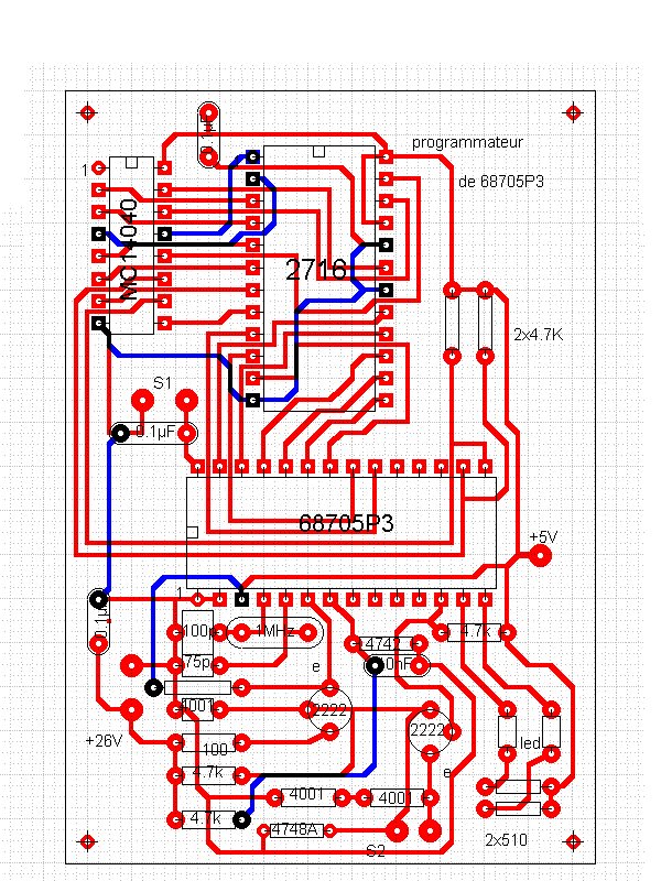
MC68705P3 Programmer diagram - implantation
MC68705P3/U3/R3 Eprom
Programming
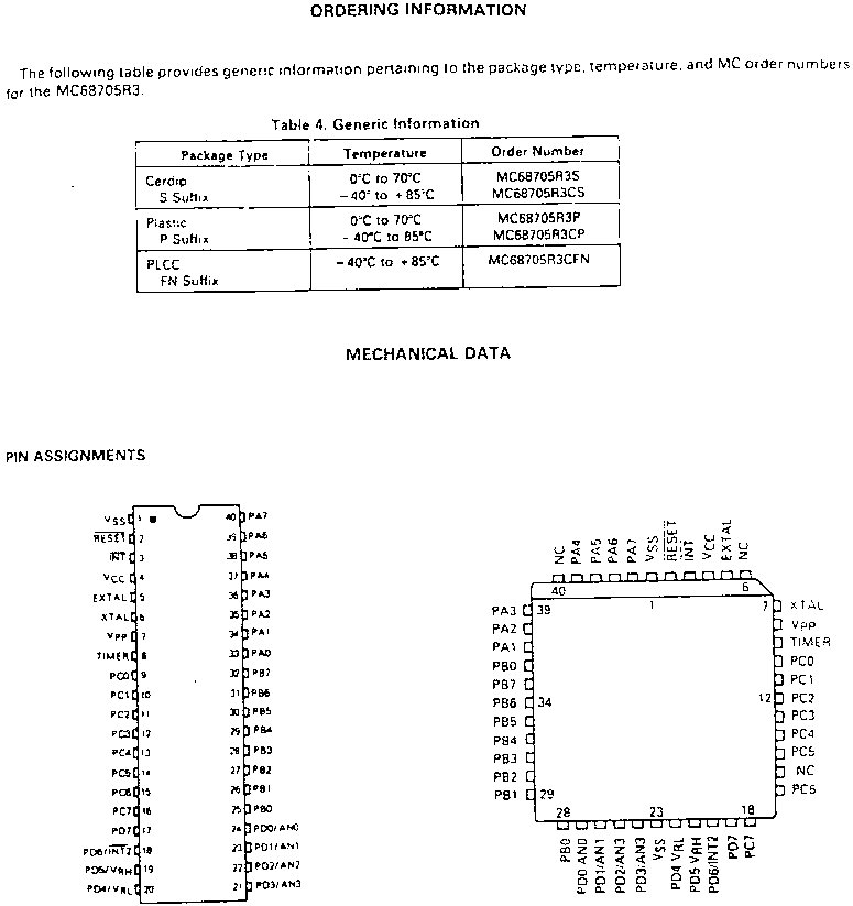
MC68705R3 pinout DIP-40/PLCC-44 cf also page 3-623 datasheet technical summary MC68705R3 databook page 3-604 Motorola microprocessor Data
***
I have a question on the MC6805U3, can the internal ROM be bypassed so you can use an external Eprom or EEprom?
The 68705U5 had a so-called NUM mode, which stood for Non-User mode. It was
proprietary technique (something weird like putting +9 volts on port C7), then
sending a certain byte sequenceon the A-port), in that you had to sign a non-disclosure
agreement with Motorola to get the details. Once in the NUM mode, external memory
could be accessed. In fact, that is exactly how the Motorola development systems
for the 68705 worked.
Now, wether it has any applicability for the 6805U3 part is not clear, but at
least in some members of this (now obsolete) family the ability was there, albeit
somewhat esoteric.
***
Motorola M6805 HMOS M146805 CMOS Family Microcomputer / Microprocessor Users's
Manual second edition contains the following data
sheets:
Complete M6805 M146805
User's Manual (PDF- 236 pages - 6.77Mb)
![]() Note
d'application Motorola AN-858 : Bicycle Computer using the MC146805G2(
)1 Microcomputer Application note - Compteur de vélo à base d'un
microcontrôleur compatible 6805 (1984 handbook)
Note
d'application Motorola AN-858 : Bicycle Computer using the MC146805G2(
)1 Microcomputer Application note - Compteur de vélo à base d'un
microcontrôleur compatible 6805 (1984 handbook)
![]() AN993 Serial-to-Parallel
Converter Using the MC68705P3
AN993 Serial-to-Parallel
Converter Using the MC68705P3
![]()
MC68705P3 Readers
![]() Chip_Service_MC68705P3_reader
documentation, schematic, pcb (PDF- 5 pages - 314Kb) - unfortunately the
firmware of the ST62T25 is not available (device secured).
Chip_Service_MC68705P3_reader
documentation, schematic, pcb (PDF- 5 pages - 314Kb) - unfortunately the
firmware of the ST62T25 is not available (device secured).
Lecteur de 68705P3S - Kit Chip Service - Le sch�ma est bas� sur un ST6225 dont le programme est verrouill� et n'est pas disponible..
MC68705P3 reader kit made by Chip Service based on a secured ST62T25B6/HWD microcontroller.
firmware not available
|
MC68705P3 Reader
|
EP705N Module et LP120 : permet entre autre la lecture des MC68705P3/U3/R3 ainsi que la programmation des MC68705P5/U5/R5 (version avec bit de sécurité).
http://a.g.electronique.free.fr/ lecteur TNT (MC68707P3/P5/R3/R5/U3/U5)- DASM
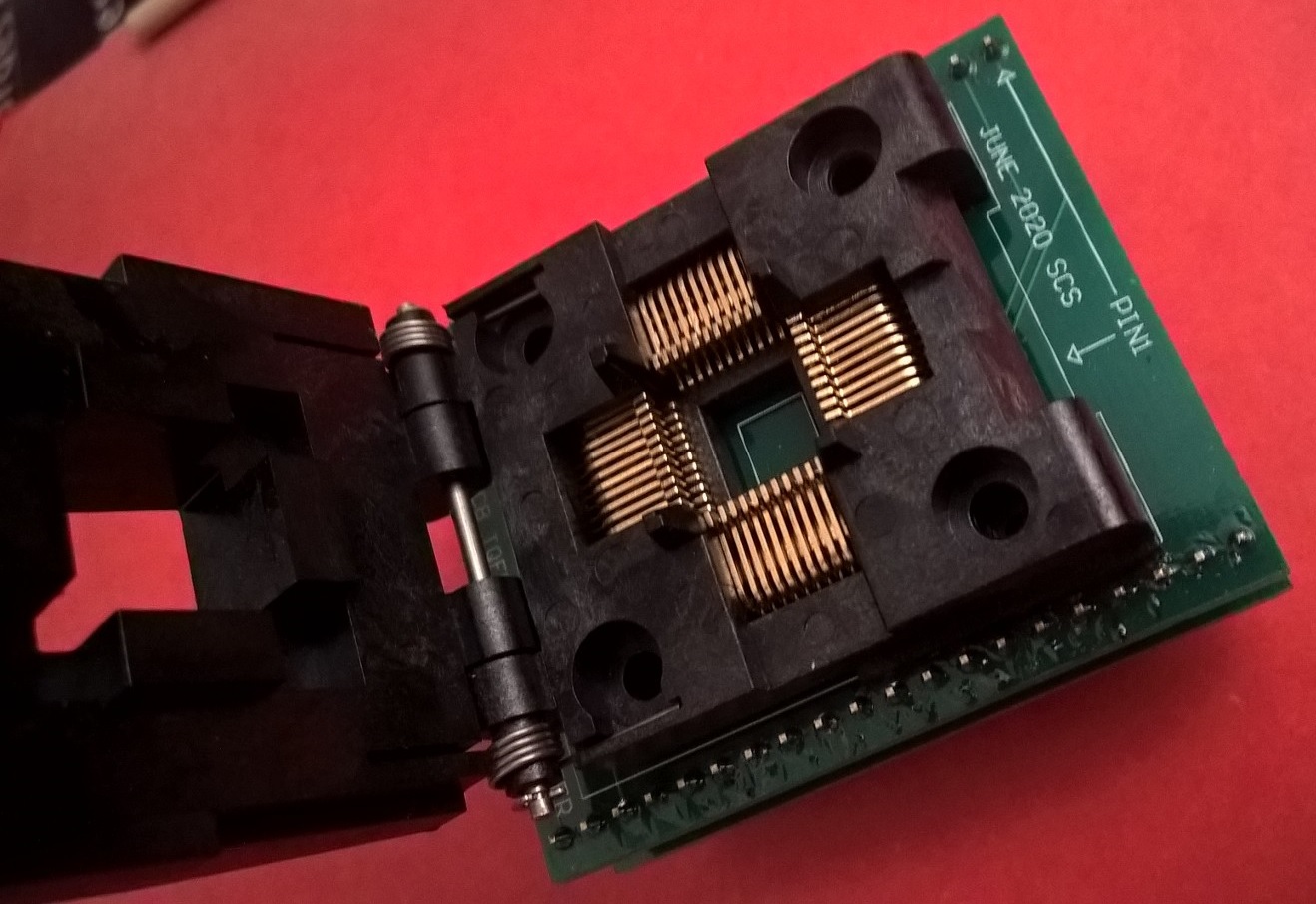
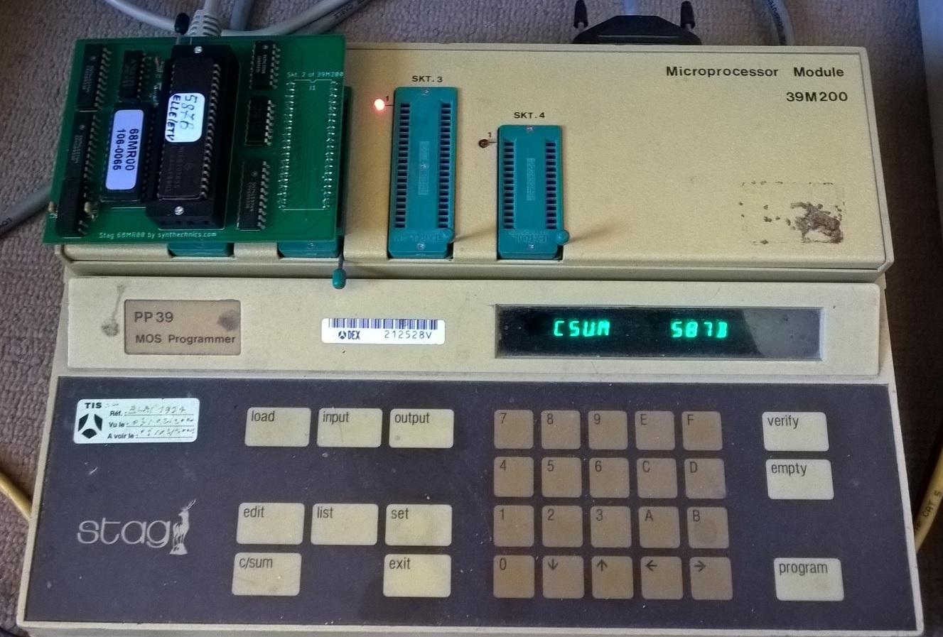
| MC68705R3 / MC68705U3 read out with a Stag PP39 Programmer and 39M200 Module and 68MR00 adapter : L'adaptateur 68MR00 de Stag Microsystems UK permet de lire le 68705R3 et 68705U3 (en moins de 1 seconde) et ce en émulant le microcontrôleur . Cet adaptateur est composé d'une Eprom et d'une connectique adaptatrice venant se fixer sur le programmateur Stag PP39. Adapter 68MR00 from Stag Microsystems UK allow you to read MC68705U3/U5(*), MC68705R3/R5(*) microcontrollers in less than 1 second by emulating the device. This adapter integrates a 27c256 Eprom chip and connector that is plugged onto the 39M200 Module of the Stag PP39 programmer.
(*) U5 and R5 can be read only if the program has not blocked the bootstrap access.
|
![]()
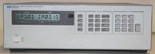
HP 6626A DC Power Supply, Precision Dual-Output, 2 at 7V/0.015A, 2 at 16V/0.2A,
GPIB
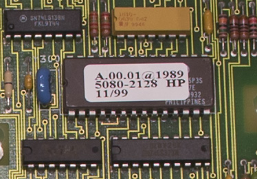
5080-2128 HP
![]()
https://felixpopineau.blogspot.com/2014/07/
REALISATION A BASE DE MICROCONTROLEUR MOTOROLA MC68705 P3S
In the 68705P3/R3/U3, how is the "contents dump" feature invoked?
In general, 68HC705s are placed into "programming mode" by applying
9V to the IRQ pin, which forces the processor to fetch its vectors from addresses
16 bytes below the "normal" vector locations. However, on the P3/R3/U3
parts, programming mode is entered by applying 12V to the TIMER pin, which shifts
the vectors downward by eight bytes.
For the P3, the "normal" vector locations are at $7F8-$7FF, so the
"programming mode" vectors would be at $7F0-$7F7. For the R3/U3, the
"normal" vectors are at $FF8-$FFF and the "programming mode"
vectors are at $FF0-$FF7.
The "programming mode" RESET vector points to the built-in "bootstrap" code (at $785-$7F7 [P3] or $F80-$FF7 [U3/R3]), which handles all programming functions. Unfortunately, the P3, U3, and R3 parts do not contain bootstrap routines for "verify" or "contents dump".
For more information, see Motorola's application note #857, "MC68705P3/R3/U3 8-Bit EPROM Microcomputer Programming Module".
Tip: Best 6805 assembler : take a look at http://www.pemicro.com/ They offer 6505 with complete environement (DOS Version "rapid") and also later versions what contains HC05 assemblers.
****************
I have been searching for a long time. Motorola does not want you to know
how to program these parts. Their programming
algorithms are proprietary. P&E micro (who makes/sells the eval boards)
will not publish this informatin either. Motorola's literature *sort of* describes
the programming but the details always seem to be lacking. I own the eval card
and use it for programming the parts, but the software is inefficient, in my
opinion. I wanted to build my own programmer and attempted to reverse engineer
how the P&E software 'force- feeds' the programming instructions to the
microcontroller, but my interest and patience wore thin and I gave up. If you
ever run across a DIY programmer, don't forget me. Send me your information..
Take care.
****************
MC68HC705C8
Battery charger / charge Analyzer with the MC68HC705C8
A http://www.opus131.com/ijs/c8a/
c8aprog, a Programmer for the MC68HC705C8A and MC68HSC705C8A
A http://www.midondesign.com/PROG05/PROG05.html
68HC705C8 programmer
https://www.nxp.com/docs/en/data-sheet/MC68HC705J1A.pdf MC68HC705J1 - cf section 2.6.1 - Note that the programming details hasn't been made public by motorola . The only thing you have to do is to buy one. For example Future Electronics (Canada) sells one for $130CDN.
Routine de gestion de bus I2C pour 68hc05 (Shift- Cliquer pour télécharger 5Kb)
Un chargeur pour programmateur de 68705 (Article RADIO-PLANS n�520 p.79-82 X.FENARD) Ce loader constitue un des maillons d'une mini-chaîne de développement pour le monochip 68705P3 de Motorola. Il s'adapte sur les programmateurs de Monochips Motorola (ou compatibles). Ces derniers étant plutôt orientés vers la duplication de monochips que vers la création de logiciels, le chargeur présenté ici en étendra les possibilités.
Programmation du microcontrôleur MC68HC705K1 (Article RADIO-PLANS n�546 p.43-49 Jean-Paul Jacquet): Boîtier à fenêtre MC68HC705K1S (Eprom) DIL16, Boitier plastique sans fenêtre MC68HC705K1P (OTP) DIL16 et le boîtier CMS MC68HC705K1S (OTP).
Programmation du microcontrôleur MC68HC705J2 (Article RADIO-PLANS n� 553 p.25-32 - J.-P. JACQUET ) Microcontrôleur compatible avec la famille HC05. Les entrées-sorties appartiennent à l'espace mémoire, il intègre 2048 octets de mémoire EPROM (incluant 16 vecteurs d'interruption),il intègre 112 octets de RAM (SRAM), il possède 14 lignes d'entrées ou de sorties. Son fonctionnement est purement statique (pas de vitesse minimum d'horloge). L'oscillateur est intégré (utilisation d'un quartz ou d'un résonateur céramique). Il intègre un "timer" multifonctions (15bits). Il intègre un circuit d'interruption (RTI). Il intègre en ROM un bootloader (programmation de son EPROM). Il possède des modes faible consommation. Il possède l'émulation du MC68HC705J1. La nature du signal d'interruption est sélectionnable (en front ou en front suivi d'un niveau). Il possède un timer (COP) il intègre la multiplication non signée 8bits x 8bits. Il existe en boîtiers DIP 20 (versions OTP), SOIC 20 broches (Versions OTP) et CERDIP 20 broches (Version à fenêtre).
Testeur de 68705P3 : (Article RADIO-PLANS n�554 p.15-17 P. ACHERNARD )
Lors d'un développement, après plusieurs reprogrammations du 68705P3, où quand le programme se bloque, on peut mettre en doute le bon fonctionnement du 68705P3. De nombreux monochips de la famille Motorola disposent d'un programme de self-test, le 68705P3 en disposera d'un maintenant grâce à cette platine de test.
![]() Un
programmateur simple de 68705P3 (Article RADIO-PLANS n�526 p.63-68 X.Fenard
) (Shift-Click pour télécharger - 2.01Mo)
Un
programmateur simple de 68705P3 (Article RADIO-PLANS n�526 p.63-68 X.Fenard
) (Shift-Click pour télécharger - 2.01Mo)
Le développement d'applications autour de ce monochip passe obligatoirement par la programmation d'un EPROM. La note d'application de Motorola est très claire à ce sujet. Dans cette nouvelle version, il n'est plus nécessaire d'avoir de mémoire intermédiaire, un PC muni d'une sortie imprimante est seulement nécessaire. Elle permet de vérifier la virginité du monochip, et peut être utilisée comme mini-système de développement. Equipée d'une alimentation à découpage, elle ne nécessite plus d'alimentation supplémentaire.
Testeur de virginité pour monochip 68705P3 (Article RADIO-PLANS n�532 p.49-51 - X.FENARD)
Ce petit montage pour le monochip 68705P3 permet de déterminer si celui-ci est vierge ou non. Couplé à une lampe UV, il permettra de connaître le temps d'exposition nécessaire à l'effacement de l'EPROM du monochip. En ajustant ce temps, il sera possible d'allonger le nombre de cycle de programmation de l'EPROM et par conséquent la durée de vie du monochip.
Un convertisseur RS232 avec le 68HC705K1 ( Article RADIO-PLANS n�549 p.29-31 P.ACHERNARD)
Les "Glues Chips" désignent en électronique les circuits périphériques d'un VLSI qui sont destinés à le coller au reste du schéma électrique. Le MC68HC705K1 peut être considéré comme un "Glue Soft" dans la mesure où il peut faire un traitement d'interface pour résoudre un problème spécifique. Dans cet exemple, nous allons voir comment gérer une liaison série avec un MC68705K1 qui ne possède pas d'UART.
Génération d'une alimentation +5V à partir du Microcontrôleur MC68HC705K1 - (Article Electronique Pratique n�224 - P.100/103) - Si votre système utilise un microcontrôleur, vous pouvez utiliser quelques ressources de ce composant comme deux broches d'entrée-sortie fournissant un courant important, un compteur, associés à un "tour d'adresse" logiciel et quelques composants extérieurs (2 diodes et 2 capacités) afin de réaliser une pompe de tension peu couteuse. Cette pompe de tension tourne en tâche de fond dans votre logiciel afin de générer en permanence la tension nécessaire de +5V.
Un chronomètre à 68705 - (Article Radio-Plans N�550 - P.43/44) Cette réalisation est propice aux détournement en tous genres, comme la réalisation d'un programmateur journalier, d'un métronome, etc. - Ce chronomètre devra fonctionner sans ordinateur (être autonome), il devra savoir compter ou décompter, gérer des relais� L'affichage a été réalisé avec des afficheurs 7 segments. Les afficheurs à LEDs consommant beaucoup, nous avons écartés d'office les versions LOW POWER (68HC705) ainsi que celles qui sont pauvres en capacité d'Eprom (le petit K1). Le 68705P3 convient. Au cas où l'applicatif deviendrait trop grand, nous passerions au 68HC705C8 mais comme d'habitude le 68705P3 sert de test. Pour une application "haut de gamme", un liaison RS232 a été prévue, le chronomètre devenant un "terminal" intelligent du PC. (composants utilisés: CD4511, MC14499, ULN2803, ULN2903, HDSP5300, 74HC(T)244, NMC9306�)
Jeu de Société (Gadget) à 68705P3 - (Article Electronique Pratique n�214-P.96/100) - Cette réalisation a pour objet d'agrémenter un jeu de société traditionnel : Recherche de code à 4 chiffres (double dé) de votre choix en moins de 1 minute, un jeu de hasard, et un décompteur associé à un buzzer. Le double dé est lancé par impulsion sur la touche A du faux clavier hexadécimal. Vous observerez alors deux chiffres glissants illisibles, le premier et le troisième en partant de la droite. Une impulsion sur la touche * bloque l'affichage sur les 2 chiffres proposés. Ceux-ci restent visibles pendant environ 4 secondes. Vous pourez ensuite relancer un nouveau cycle. Si vous appuyez sur une autre touche que *, vous observerez l'arrêt du défilement qui reprendra dès que vous la relâcherez. (circuits utilisés: MC68705P3S, MC14499, Quartz 3.2768 MHz, Aff. Cathode commune TDSR 5160�)
Ensemble Domotique Modulaire de 6 sorties configurables en télérupteurs, gradateurs ou minuteries. - (Article Electronique Pratique n�221 - P.53/67) : Carte alimentation, Carte microcontrôleur, carte sortie à relais, carte pupitre, carte à triac, carte gradateur. Montage sur Rail DIN.
Pr�sentation du 68HC705K1 (Article RADIO-PLANS n�545 - P.46/47)
An LCD and Keypad Module for the SPI with 68HC705K1P (Circuit Cellar INK #57 - Avril 1995)
Le 68705 -Pr�sentation (Electronique Pratique n�164- P.139-141 par X.FENARD)
Attente et transfert t�l�phonique TSM � 68705P3 programm� Attel (El. Pratique n�157/P.97-100)
T�l�flic � 68705P3 1995, Elektor magazine, International Contest "Projets en Compétition"
: First National price, for Téléflic
Surveillance d�port�e de chaudi�re au fioul (68705P3) Elektor Janvier 1996
A Learning Remote-Controlled (IR) Speaker Selector � 68HC705K1(Circuit Cellar issue #57 - Avril 1995)
Le MC68705P3 et son utilisation pratique - programmateur de 68705P3 (Revue LED -P.12/33)
Programmateur de 68HC705C8 - Retour sur le Programmateur de 68HC705C8 - Le 68HC705C8 en PLCC (Articles de X.FENARD parus dans Electronique Radio-Plans N�540,566, et 541.)
Adding New Addressing Mode in the 6805 Microcontroller - Extrait de Don Lancaster's Tech Musings Novembre 1995
![]()
|
d'après les articles de E.DERET parus dans Hobbytronic n°10,14
et 17 Peut servir pour la commande d'arrosage par exemple.
mc68705P3 memory contents uniprog2 universal programmer (binary file- 2Kb) |
![]()
Microprocesseur MC146805ELP
Il s'agit d'un 6805 N-MOS des Années '80 Das "E" bedeutet typisch
"externer Speicher", d.h. es ist hoffentlich irgendwo ein EPROM auf
der Leiterplatte.
MC146805E2 war relativ gängig. 68HC05E2 war der angeblich voll kompatible
CMOS-Nachfolger. Davon habe ich das Thomson-Datenblatt. Gabs in DIL 40 oder
PLCC44.
![]()
Hilosystems Programmers : programming adapter for MC68705P3
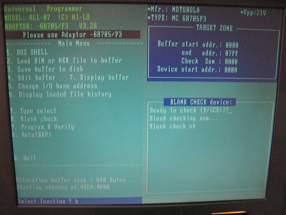
Blank checking of the MC68705P3 with Hilo ALL-07A programmer and adapter ADP-68705/P3
Schematic and information about adapter ADP-68705 See 120.htm for hilo programmers.
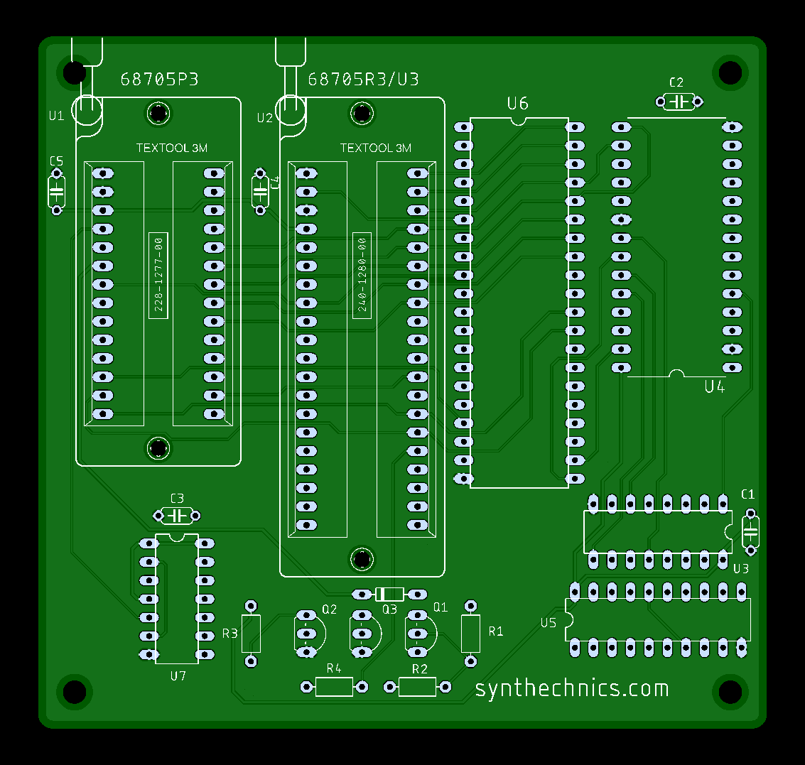

new pcb courtesy Amilcar (Portugal)


![]()
https://github.com/philpem/68hc705_glitcher 68HC705C8 Glitcher
NXP Freescale MC68HC705C8A TQFP to DIP programming Adapter

ADP-68HC705 Adapter to program MC68HC705C8 with hilosystem ALL-03 / ALL-07 /
ALL-11 programmer.
Note: this adapter do not support read out

Programming MC68HC705C8 with Hilo programmer ALL-03
![]()
![]()
https://pestingers.net/pdfs/other-computers/circuit-cellar/1992/circuit-cellar-026.pdf programming the MC68HC705C8 by Edward Oscarson page 52-68

![]()
- Motorola MC68705P3 HMOS (High-density N-channel depletion load, 5V eprom
process) 8-Bit Eprom microcomputer Advance Information [pages 3-859 to 3-882
databook Motorola dec.1990]
- Motorola Semiconductor technical data MC68705R3 Technical Summary [databook
pages 3-604 to 3-623 Motorola]; page 3-623 indicates the wiring of the DIP-40
and PLCC-44 packages.
- 68HC05 Family (Sheets 1 to 4) contains documentation references, comments
and characteristics of 68HC05 devices.
- Don Lancaster's Tech Musings November, 1995 : adding new addressing modes
to the 6805 microcontroller : A 6805 Programming Trick.
- An LCD and Keypad Module for the SPI (Circuit Cellar IN Issue #57 April 1995
page 36 to 45 (MC68HC705K1P)
- Game : find a 4-digit code of your choice in less than 1 minute : based on
MC68705P3 and MC14499 with cc 7-digit led displays & 16-keys keypad [Article
from B.GIFFAUD Electronique pratique N°214 p.96-100]
- 68HC705B16 Microcontroller Features
- 68HC705P6A Microcontroller Features
- AN1736 Rev.1 Application note : HC705P9 to HC05P6
- A Learning Remote-Controlled Speaker Selector Design Contest winner from Scott
Heiserman & Clark Oden based on MC68HC705K1 [Circuit Cellar INK April 1995
p.75-81]
- Presentation of the 68HC705K1 [Article
from J-P. Jacquet published in Electronique Radio-Plans N°545 p.46-48]
- +5V power supply generated from a 68HC705K1 [Electronique
Pratique N°224 p.100-102]
- Glue chips : RS232 converter done with the 68HC705K1 [Article
from P.ACHERNARD published in Electronique Radio-Plans N°549 p.29-31]
- A simple 68705P3 programmer [Article
from X.Fenard published in Electronique Radio-plans N°526 p.63-68]
- DASM05.DOC
- LED No 100 68705 copier TNT [Article from Jean-Jacques LEMOINE, B.Oldoni,
DASM05 from A.Guillaume]
- 68HC705C8 programmer [Article
from X.Fenard published in Electronique Radio-Plans N°540 p.37-41 -
Update about the 68HC705C8 programmer [X.B.
& X.Fenard Electronique Radio-Plans N°566 p.41-42] - DIP-40 to PLCC-44
Adapter and informations [Article
from X.Fenard Electronique Radio-Plans N°541 p.89-93]
- MC68HC705J2 microcontroller programming [Article
from J.-P. Jacquet Electronique Radio-Plans N°553 p.25-32]
- MC68HC705K1 programming Module [Article
from Jean-Paul Jacquet Electronique Radio-Plans N°546 p.43-49]
- MC68705R3, U3, P5, U5 Programming Connections Schematic Diagram
- LP120 Lucid Technologies programming Module
- MC68705P3/R3/U3 programmer netlist from Mark Zenier
- A loader for 68705 programming
- 68705P3 cross assembler
![]()
- MC1468705G2 Programming Schematic Diagram

here is a programmer schematic. You can see it can verify without
programming, but it
adresses the EPROM itself; I thought that it might be possible to read it
like a EPROM?
If PC0 is held low, it forces a verify loop like the programming loop. I
dont have an
explanation for S4 or S5 in the schematic, but S3 is mentioned as the switch
prog&verify
when put high, and verify only when its low.
https://www.siliconchip.com.au/Issue/SC/2025/January/Extracting+Data+from+Micros Extracting data from a MC1468705G2
![]()
- 68705P3 blank check verify [Article
from X.Fenard published in Electronique Radio-Plans N°532 p.49-51]
- 68705P3 testing : [Article
from P.ACHERNARD published in Electronique Radio-Plans N°554 p.15-17]
- 68705 description [Article
from X.FENARD published in Electronique Pratique N°164 p.139-141]
- 68705 based time counter [Article
from P.Achernard published in Electronique Radio-Plans N°550 p.43-47]
includes HDSP-3903
led displays , ULN2803, NMC9306 and programmed MC68705P3
- Modular domotics System based on MC68705P3 [Article from B.GIFFAUD published
in Electronique
Pratique N°221 p.53-67] ; 221-53
- Electrically Erasable Programmable ROM : MC68HC05B6 : EEPROM read, erase,
programming, protect operations
- MC68HC05B6 Serial Communications Interface (SCI)
- MC68705P3 practice [Article from M.ESTEVES published in LED
Magazine N°56 & 57
p.12-33] - Le MC 68705 P3 et son utilisation pratique revues LED N°56 et
57
![]()


![]()
If you are looking forward some data about this products, you can contact me
by e-mail at matthieu.benoit@free.fr
![]() 24 mai, 2026
24 mai, 2026


 Retour au sommaire
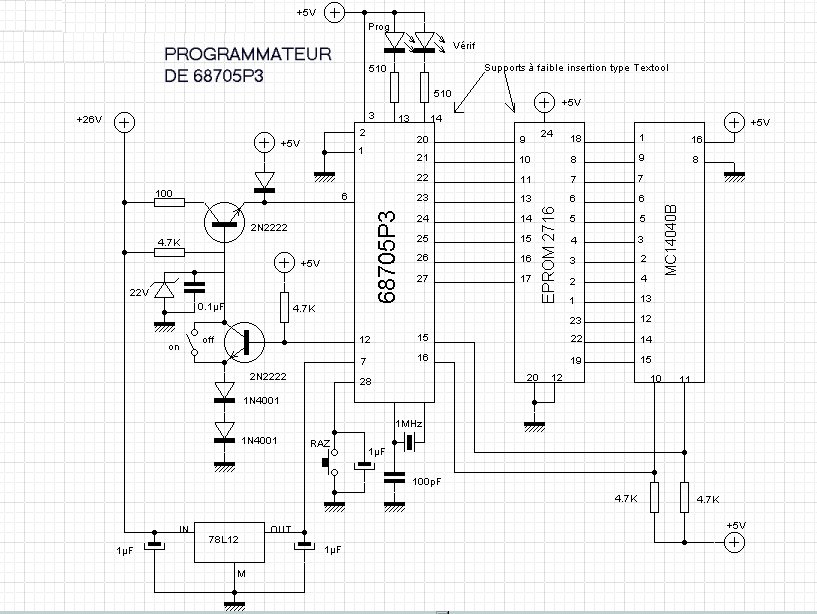