
Dťtecteur de l'appelant compatible France Tťlťcom ŗ base du MC68HC11A1P de Motorola
CallerID Unit based on Motorola MC68HC11A1P & MC145447P chips compatible with the standard protocols
![]() Correspondance
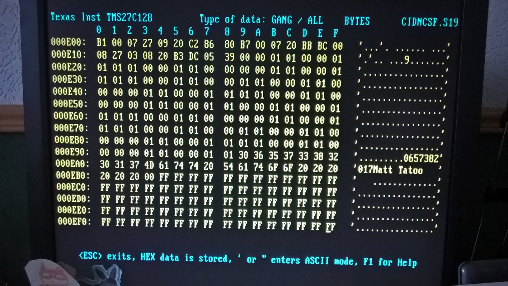
d'un rťpertoire de 17 noms / 17 Numťros de tťlťphone intťgrťe (sauvegarde permanente
dans les 512 octets d'EEPROM interne du Microcontrôleur MC68HC11A1P)
Correspondance
d'un rťpertoire de 17 noms / 17 Numťros de tťlťphone intťgrťe (sauvegarde permanente
dans les 512 octets d'EEPROM interne du Microcontrôleur MC68HC11A1P)
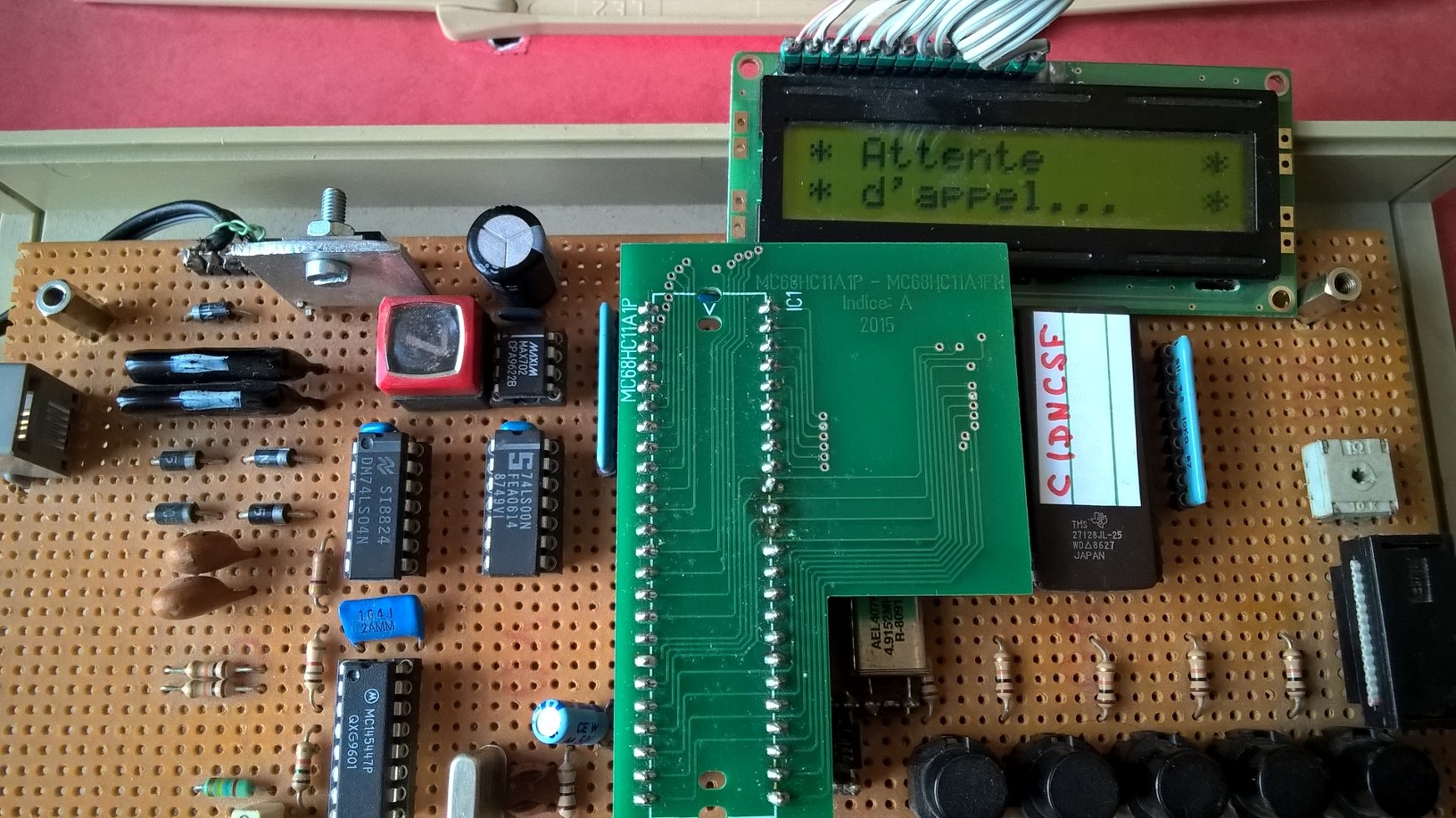
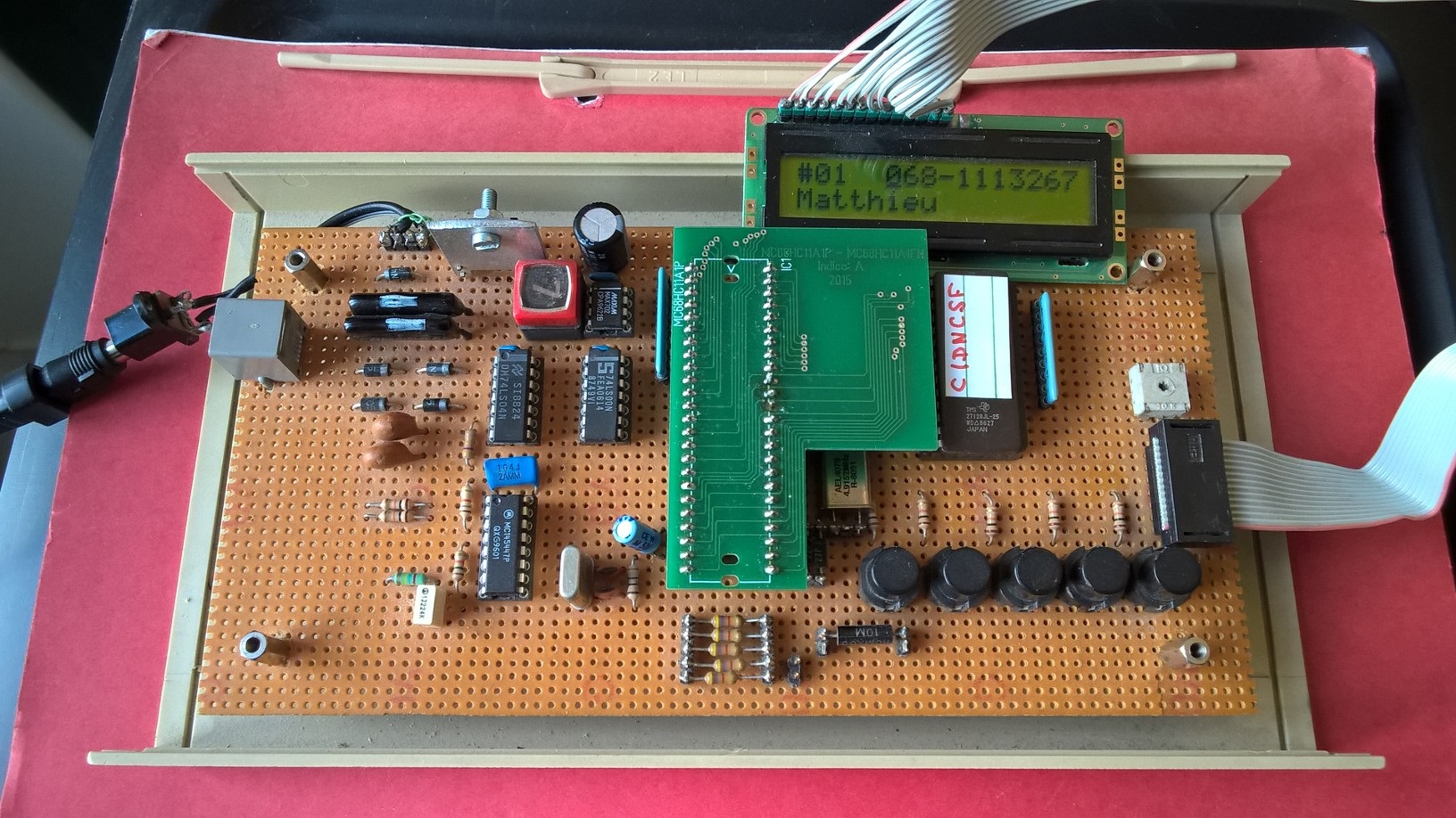
![[prťsentation de la maquette]](images/cidfr.jpg)
Callid- Identification de l'appelant
![]()
![]()
![[attente d'appel!]](images/waitcall.jpg)
cidncse
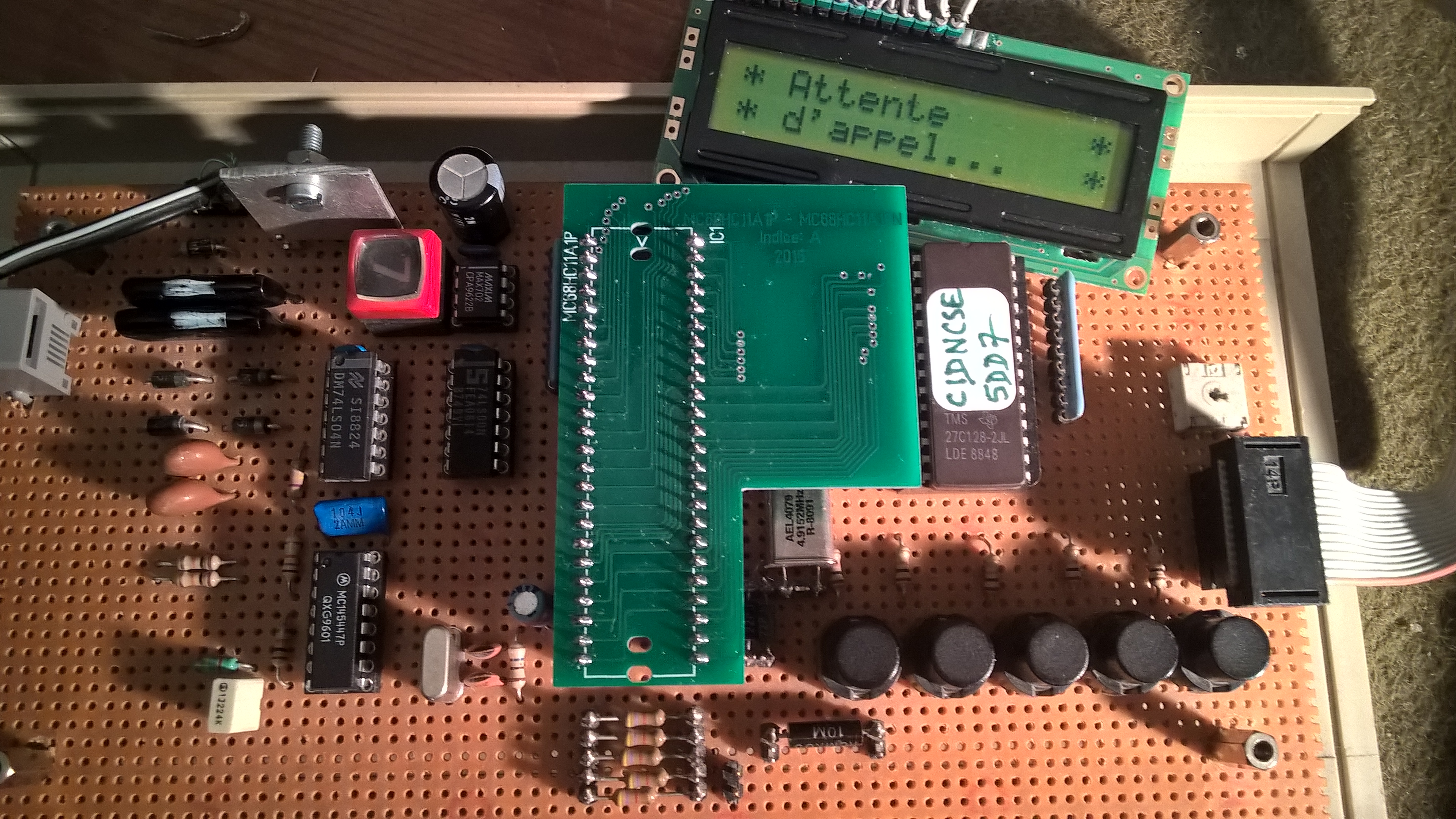
MC68HC11A1P version cidncse checksum 5DD7
![]()
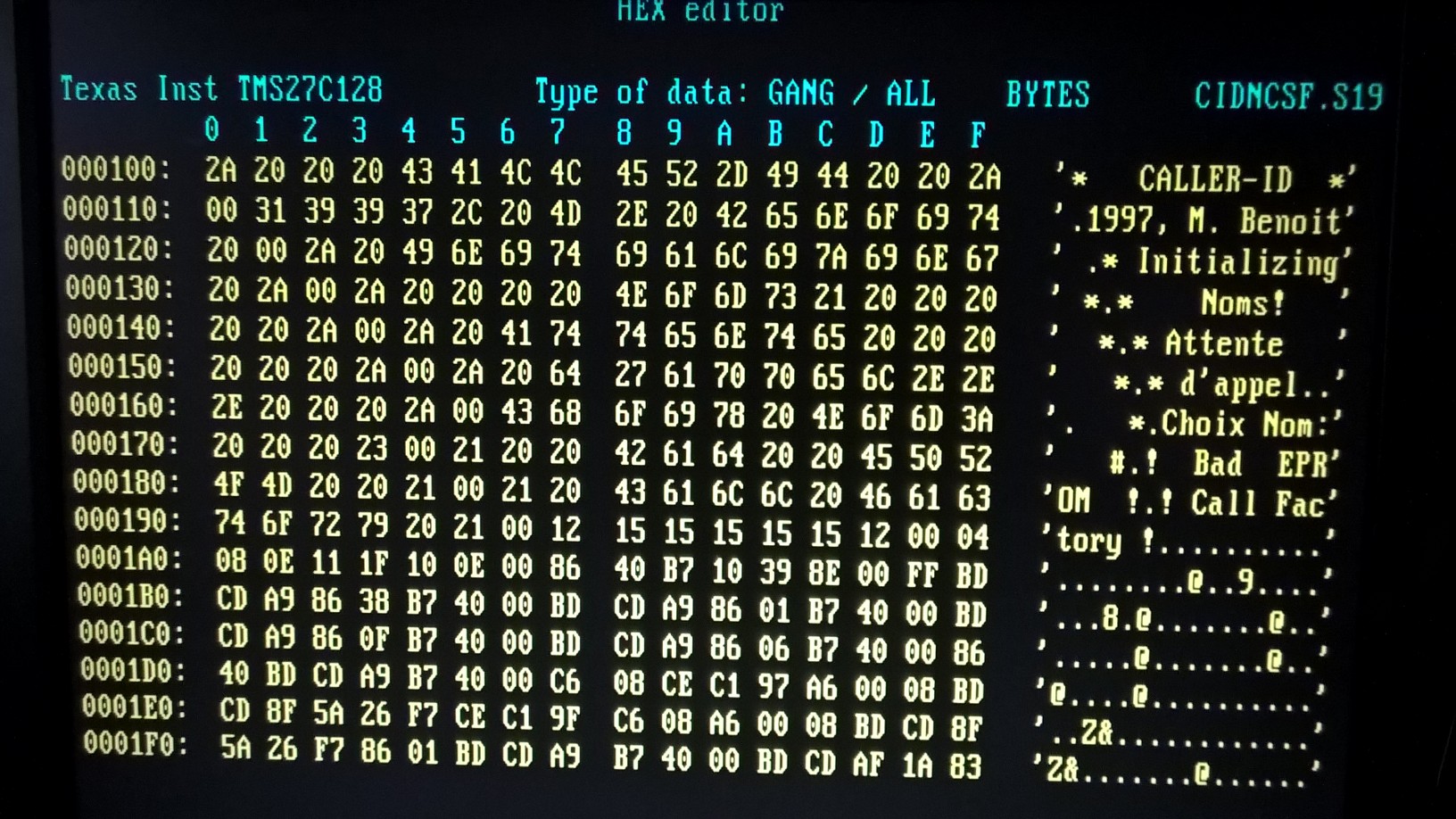
cidncsf (last update)
cidncsf.asm assembled with AS11
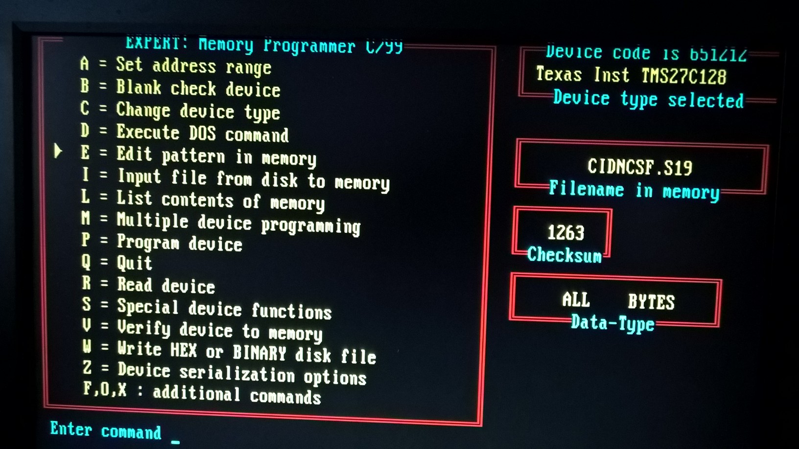
![]() cidncsf.s19
(.S19 - 9Kb) Checksum 1263 EPROM 27C128
cidncsf.s19
(.S19 - 9Kb) Checksum 1263 EPROM 27C128
![]() cidfr_cidplus.pdf (PDF - 4 pages
- 294Kb)
cidfr_cidplus.pdf (PDF - 4 pages
- 294Kb)
![]() cidplus.pdf (PDF- 162Kb) schematics
cidplus interface
cidplus.pdf (PDF- 162Kb) schematics
cidplus interface
cidplus_KiCad (directory)
![]()
![]()
![]()
![]()
![]()
Introduction:
France Telecom met en place progressivement ( depuis le 2 septembre 1997), pour 10 Francs hors taxes par mois, le service dit de "Prťsentation du Numťro": pour savoir qui vous appelle avant de dťcrocher.
Le "Secret Permanent" ( accessible en tťlťphonant au ![]() 0800803800
- Numťro Vert) et le "Secret Appel par Appel" (Il
vous suffit de composer le 3651 avant le numťro de votre correspondant) pour
que votre numťro ne soit pas prťsentť.
0800803800
- Numťro Vert) et le "Secret Appel par Appel" (Il
vous suffit de composer le 3651 avant le numťro de votre correspondant) pour
que votre numťro ne soit pas prťsentť.
Description:
Le dťtecteur de l'appelant prťsentť ici est basť sur l'ťtude de Grant Beattie
du Northern Alberta Institute of Technology (NAIT) d'Edmonton, Canada
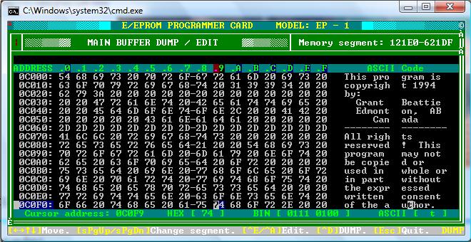
Il a ťtť adaptť pour le protocole de France Telecom (version finale 18-01-1998).
Le synoptique du montage est donnť ci-dessous.
L'archive originale est disponible sur ce serveur: elle comporte en particulier les schťmas aux formats Orcad SDTet postscript:
callid.zip Archive originale - 55Ko Shift-Cliquer pour tťlťcharger
plus de ressources disponible sur la page http://musictechnologiesgroup.com/HC11/
et http://musictechnologiesgroup.com/projects.htm
Mise ŗ jour code EPROM (support d'un rťpertoire de 17 noms (16 caractŤres) et
numťros (10 chiffres): ŗ implanter dans l'EPROM (Adresse de base $0C000):
![]() cidnom.s19
cidnom.s19 ![]() code EPROM version française avec support du rťpertoire 9Ko Shift-Cliquer
pour tťlťcharger
code EPROM version française avec support du rťpertoire 9Ko Shift-Cliquer
pour tťlťcharger
L'architecture de la carte CID-PLUS (MC68HC11A1FN) est celle utilisée pour les développements futurs . Si vous voulez réaliser ce detecteur de l'appelant je vous conseille de prendre l'architecture de la carte cid-plus. N'hésitez pas à me contacter pour connaître les modifications à apporter.
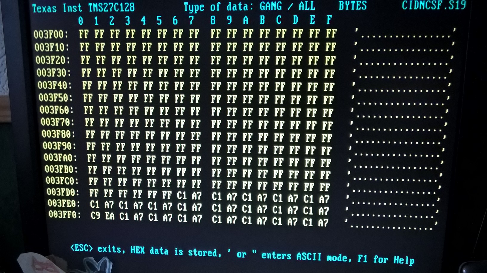
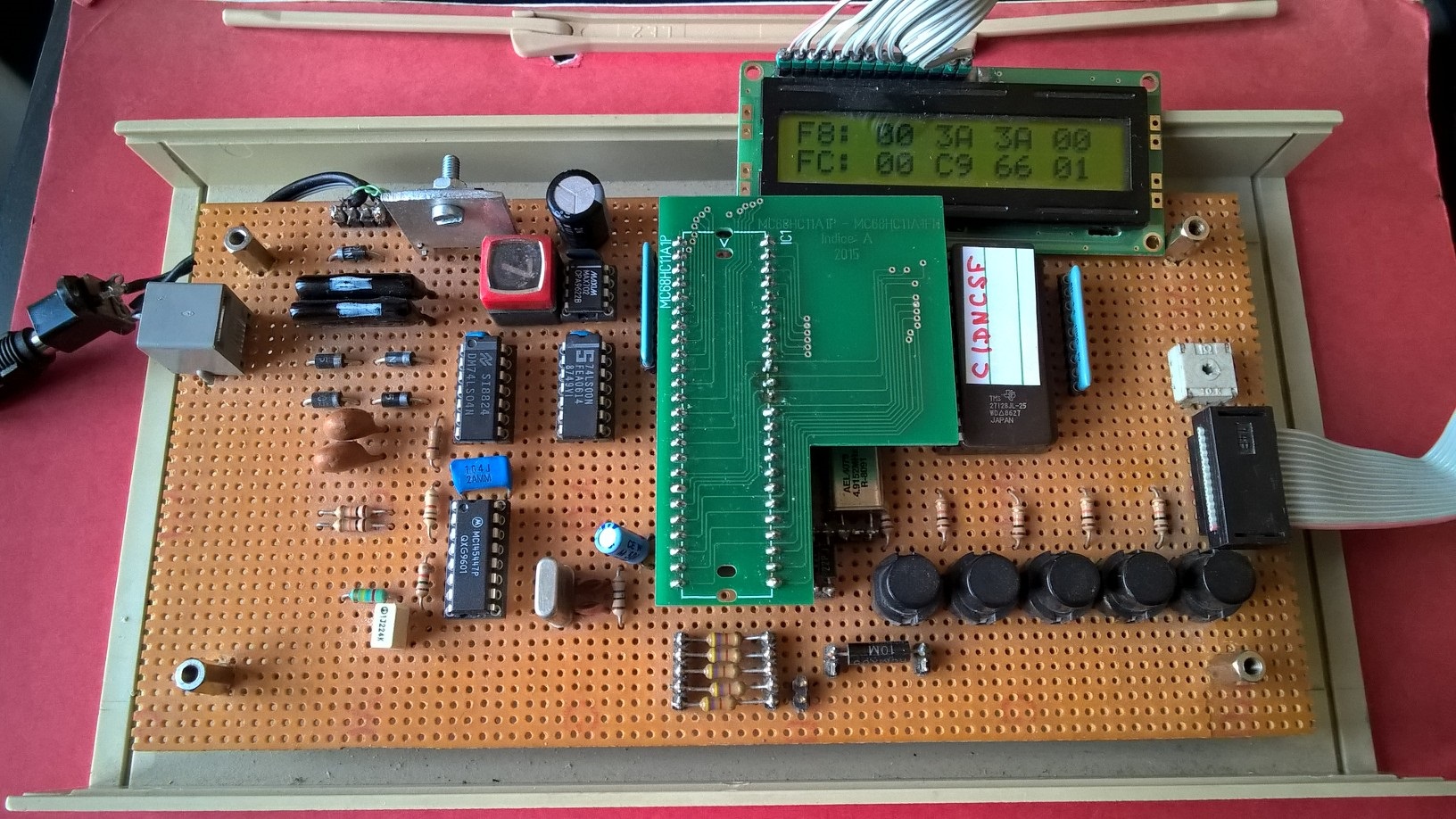
![[affichage de la RAM interne]](images/editram.jpg)
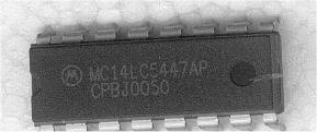
![]() MC14LC5447 data sheet
MC14LC5447 data sheet
Ci-aprŤs vous trouverez le schťma et des explications d'une interface Caller Id avec un port sťrie (d'un P.C. par exemple). Le programme de dťcodage n'est pas donnť mais tout est donnť pour dťcoder ou dťcrypter les informations arrivant du port sťrie. Ce document est une traduction d'un article amťricain, mais il se trouve que les informations sur le protocole sont celles utilisťes par France Telecom. Les informations concernant les frťquences sont des indications sur les frťquences aux Etats-Unis; une note indique la correspondance avec les frťquence utilisťes en Europe.
![]() codage.pdf Explication du codage des trames Caller ID en France (Format
PDF) - 8 Ko - Shift-Cliquer pour tťlťcharger
codage.pdf Explication du codage des trames Caller ID en France (Format
PDF) - 8 Ko - Shift-Cliquer pour tťlťcharger
Projet d'un dťtecteur de l'appelant avec un DSP.
Interface tťlťphonique intelligente compatible France
Tťlťcom ŗ base du N80C32 d'Intel et du circuit modem
TSC73K321L-IP de
TDK Semiconductors. Mise en oeuvre d'une gestion I2C du gťnťrateur DTMF PCD3312
de Philips Composants.
Vous trouverez dans le lien ci-aprŤs une façon de tester un montage
d'identification de l'appelant ou de leurrer une personne sur l'indication de
prťsentation du Numťro. Ceci avec un PC muni d'une carte sonore.
Simulation de l'identification de l'appelant
http://www.circuitmaestro.com/Projects/CCID/ Caller-Id Sans fil
http://www.rogercom.com/pparalela/Lpt-ID.htm
LPT-ID - IDENTIFICADOR DE CHAMADAS POR SINALIZAÇÃO DTMF
Comment Vťrifier si votre modem supporte l'identification
de l'appelant et ťventuellement activer cette fonctionnalitť (vu que dans
la majoritť des cas elle est dťsactivťe par dťfaut).
Documents de rťfťrence France Télécom:
B 14-10W 1995: Interface
de rťception de l'identitť du demandeur et de la notification pour terminaux
analogiques
E 13-06W 1996: Caractťristiques
de l'interface usager-rťseau pour l'identification du demandeur en phase d'appel
et la notification immťdiate d'un usager
CSE E 11-12W: identification
du demandeur en phase d'appel
CSE E 11-13W: Notification
immťdiate d'un usager (AIM)
CSE E-13-06W: Caractťristique
de l'interface usager-rťseau pour l'identification du demandeur en phase d'appel
et la notification immťdiate d'un usager (AIM)
CSE 11-11: pour l'homologation
Poste Tťlťphonique Electronique de Base
(cette spťcification sera remplacťe par la B 11-10 H)
CSE 11-23A: pour l'agrťment
Spťcification d'agrťment pour les ťquipements terminaux simples reliťs ŗ une
interface d'abonnť analogique du rťseau Tťlťphonique commutť Public
Documents ETSI:
Calling Line Identification Presentation (CLIP) Supplementary service
DE/NA-010023 version 2 rev 2,
1994-9-8
Signalling Protocols And Switching (SPS)
PSTN Protocol Over The Local Loop For Display (And Related) Services
Part 1 - On hook data transmission
work item No: DE/SPS-3034-1,
17 March 95
Recommandation V23 du C.C.I.T.T.
A http://www.ainslie.org.uk/callerid/cli_faq.htm FAQ, modem, modems, telephone, telephones, Caller ID, CLI, Caller
http://users.atw.hu/majki/elektro/mcu/project/cid/cid.htm Une interface Caller ID à base du circuit Mitel ( zarlink ) MT8843 et du PIC16F872 associé à une eeprom 24LC32.
Telephone Tip/Ring Tester Schematic
Look here:
http://www.ee.washington.edu/circuit_archive/circuits/F_ASCII_Schem_Tel.html
or here:
![]() http://www.imagineeringezine.com/PDF-FILES/2phostat.pdf
http://www.imagineeringezine.com/PDF-FILES/2phostat.pdf
or here:
http://www.educypedia.be/
if you got a multimeter and a phone you can start testing. Check the voltage
across the pair, should be 48VDC in US, 60VDC in Europe.
Place a 600 ohm resistor, 5W across the pair and measure the current should
be 20 to 40mA (holding current)
While on-hook the Ring will have a negative voltage and the Tip will be grounded
through equipment at the Central Office UNLESS the office is a "Floating
Battery" type office. In the latter case the Ring will have a negative
voltage and the Tip will have a positive voltage. The sum of the two voltages
(which are in series) will be about 48 to 52 Volts.
The usual way of doing this is to use a bicolor LED that glows read with one polarity and green when the polarity is reversed. You just put a resistor in series to limit the current. I think the ones I have usre 3.3k, maybe more if the voltage is high. the max current for a phone line is 60 mA, so it would be wiuse to put 3 or 4 diodes in series in each direction to absorb any excwess current above 20 mA or so. But the dissipation of the resistor may be more than a half watt. So use a couple in series or a 1 watter.
BTW, if you plug one of these into a wall jack, the polarity will be correct,
but the modular line cord flips the polarity so that it's
reversed at the phone jack. So you have to know where you're testing.
More info is on comp.dcom.telecom.tech newsgroup.
*******
![]()
![]() Pour plus de renseignements
quant ŗ cette ťtude et ŗ l'adaptation française ainsi que si vous avez
des conseils sur le sujet, vous pouvez me contacter ŗ l'adresse suivante: matthieu.benoit@free.fr
Pour plus de renseignements
quant ŗ cette ťtude et ŗ l'adaptation française ainsi que si vous avez
des conseils sur le sujet, vous pouvez me contacter ŗ l'adresse suivante: matthieu.benoit@free.fr
![[Synoptique de l'application]](images/syncli.jpg)
Le montage dťcrit dans cette page revient environ ŗ 60 Euros!. Je l'ai rťalisť
en wrapping et donc je ne peux vous donner ŗ ce jour de circuit imprimť; (celà
se fait en 1 WE et demi).
![]()
Amťliorations du programme
~~~~~~~~~~~~~~~~~~~~
![]() Version
actuelle en cours de développement CID-PLUS
Version
actuelle en cours de développement CID-PLUS
![]() Répertoire supplémentaire
'illimité' en EPROM programmé à la conception.
Répertoire supplémentaire
'illimité' en EPROM programmé à la conception.
![]() Extension d'un répertoire
éditable en EEPROM Externe (X25128
SPI) (16Kb)
Extension d'un répertoire
éditable en EEPROM Externe (X25128
SPI) (16Kb)
![]() Gestion d'une imprimante
Point Of Sale OEM type M-180
EPSON SEIKO Instruments pour l'impression des appels (PIA, Motor Controller)
Gestion d'une imprimante
Point Of Sale OEM type M-180
EPSON SEIKO Instruments pour l'impression des appels (PIA, Motor Controller)
![]() Affichage que l'appel vient
d'une cabine publique (numťro se terminant par 24,35,42,53,68
ou 86)
Affichage que l'appel vient
d'une cabine publique (numťro se terminant par 24,35,42,53,68
ou 86)
![]() Affichage en double appel
: il faudra utiliser un autre circuit du type CMX602B
(remplaçant du FX602P) de Consumer
Microelectronics (CML) et rajouter le dťcodage des octets prťvus dans ce cas
par la norme de France Telecom.
Affichage en double appel
: il faudra utiliser un autre circuit du type CMX602B
(remplaçant du FX602P) de Consumer
Microelectronics (CML) et rajouter le dťcodage des octets prťvus dans ce cas
par la norme de France Telecom.
(Note: Les numťros des mobiles ITINERIS sont transmis depuis le 10 Juin 1998
de faÁon transparente comme un numťro normal.)
cidplus
![]()
![]() Caller ID printer Module (PDF
- 6 pages - 5.96Mb)
Caller ID printer Module (PDF
- 6 pages - 5.96Mb)
Retour ŗ l'index 68hc11
![]()
Note sur la nouvelle numťrotation de France Tťlťcom
Les indicatifs tťlťphoniques de la rťgion parisienne et de la province
![]()
Voici des liens concernant 2 montages à base de 89C2051 (CI compatible
8051) utilisant la présentation du n°. - 1 avec affichage sur LCD
2x16 et 1 sur TV avec incrustation du n° ou nom de l'appelant en bas de
l'écran.
A http://vesta.homelinux.free.fr/v/wiki/presentation_du_numero_de_telephone_cid_sur_lcd.html
A http://vesta.homelinux.free.fr/v/wiki/presentation_du_numero_de_telephone_cid_sur_tv.html
Cela gère aussi la messagerie Top-Message®.
************
Voyant Top Message
Ce n'est pas si simple, il faut extraire la trame envoyée par FT juste après la première sonnerie avec un démodulateur FSK, puis interpréter son contenu avec un micro-contrôleur.
cf. A http://www.webilis.com/electro/clid/clid_1.html.
Dans le cas du
Top Message, le premier octet de la trame est 82h au lieu de 80h,
les
paramètres date/heure sont les mêmes, le numéro de l'appelant
est celui de
Top Message (3103, ...). Un paramètre supplémentaire indique
la présence ou
l'absence de message:
0B,01,FF
pour signaler la présence de messages
ou
0B,01,00 pour signaler
qu'il n'y a plus de message.
************
https://www-user.tu-chemnitz.de/~heha/basteln/Haus/Telefon/CLIP-Dekoder/
Questions & Answers:
Question: Anybody got code to decode DTMF tones on a PIC.
Note that the question is NOT, "can I read an external DTMF decoder using a PIC?"
Can I stuff DTMF audio into the PIC A/D and decode the DTMF in
software?
I need the pic for some other simple funtions, but it's doing mostly nothing.
Can I apply that unused power to decoding DTMF and save the space and power
dissipation of the DTMF decoder chip?
answer1: There are lots of variants of PIC, with significant variations
in instruction set, speed, and memory capacity. Yes, you *could* use any microcontroler
to decode DTMF, sort of. Counting the times between pulse-peaks and turning
them into a frequency and thence into a DTMF digit can be done with any sufficiently
fast microcontroller. The problem comes in detecting whether the stuff being
input really is DTMF. If the PIC has to start decoding DTMF in the presence
of noise, or has to discriminate it from speech, then you're into the realms
of DSP, which is not really what PICs are about.You want to connect the audio
input to the ADC port, which suggests that you want to do more than simple time-between-peak
detection. I suppose you could precompute the sine-wave patterns of the frequency
-pairs of the DTMF digits in whch you're interested, and then try and match
them up.In any case, if I were wanting to do this, I'd want to dedicate a PIC
to the job, and not have it doing other things. So, you're back to needing an
additional device anyway, which you don't want to do.
answer2: TI has a application note SLAAE16.pdf about decoding
dtmf with msp430. you can convert it for pic ( i used avr, it works, but has
poor noise immunity. reason is too low sample frequency. later i increased sample
rate to 15khz and wrote new filters, but this take about 8 mips from "mul"
supported avr ) .
The other way is to use external lp and hp filter for separating low and high
frequence groups, and use goertzel algorhitm. I guess on ubicom webpage is another
appl.note about decoding dtmf .
answer3: Once you have the lp and hp filters, the PIC should be quite suitable, if you add zero crossing detectors. Then you measure periods, form moving averages and reject deviations. I built such a system with very slow CMOS over 30 years ago, with the idea of integrating it into the then existing cheap PMOS technology, and got excellent acceptance _and rejection_ performance.My front end, including zero crossing and filters, consisted of one quad opamp. Cross channel hysteris control took care of amplitude relationships, i.e. peak amplitude on one channel set the hysteris on the the other channel.
answer4: This link may be of use: http://www.dattalo.com/technical/theory/dtmf.html
http://www.adventinstruments.com/Resources/
http://web.archive.org/web/20060713015251/http://www.adventinstruments.com/resources/semi.htm
Caller Id semiconductors
http://electronique.marcel.free.fr/CLIP.html
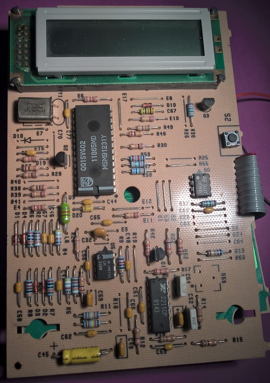
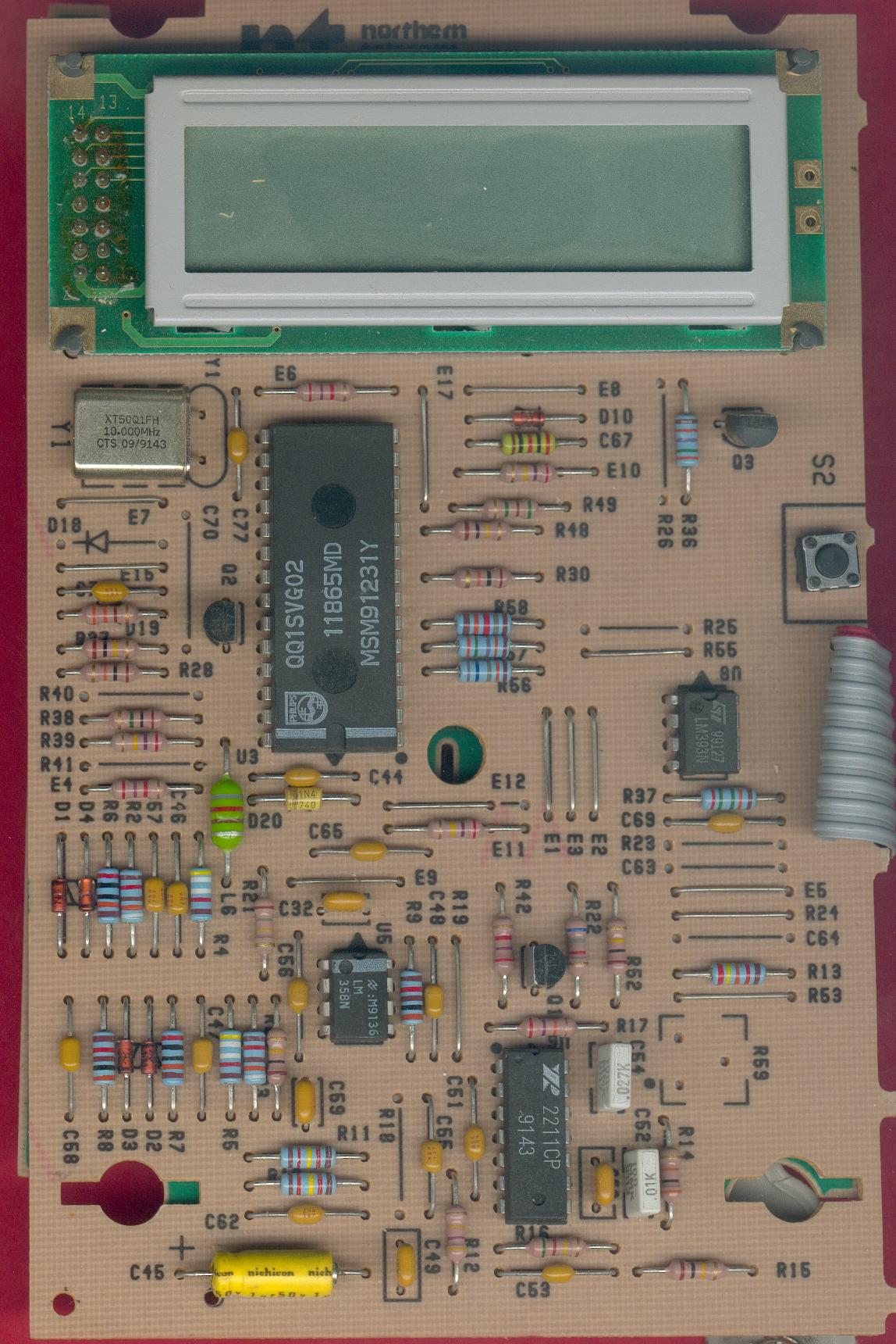
Appareil autonome affichant les numéros appelants
![]()
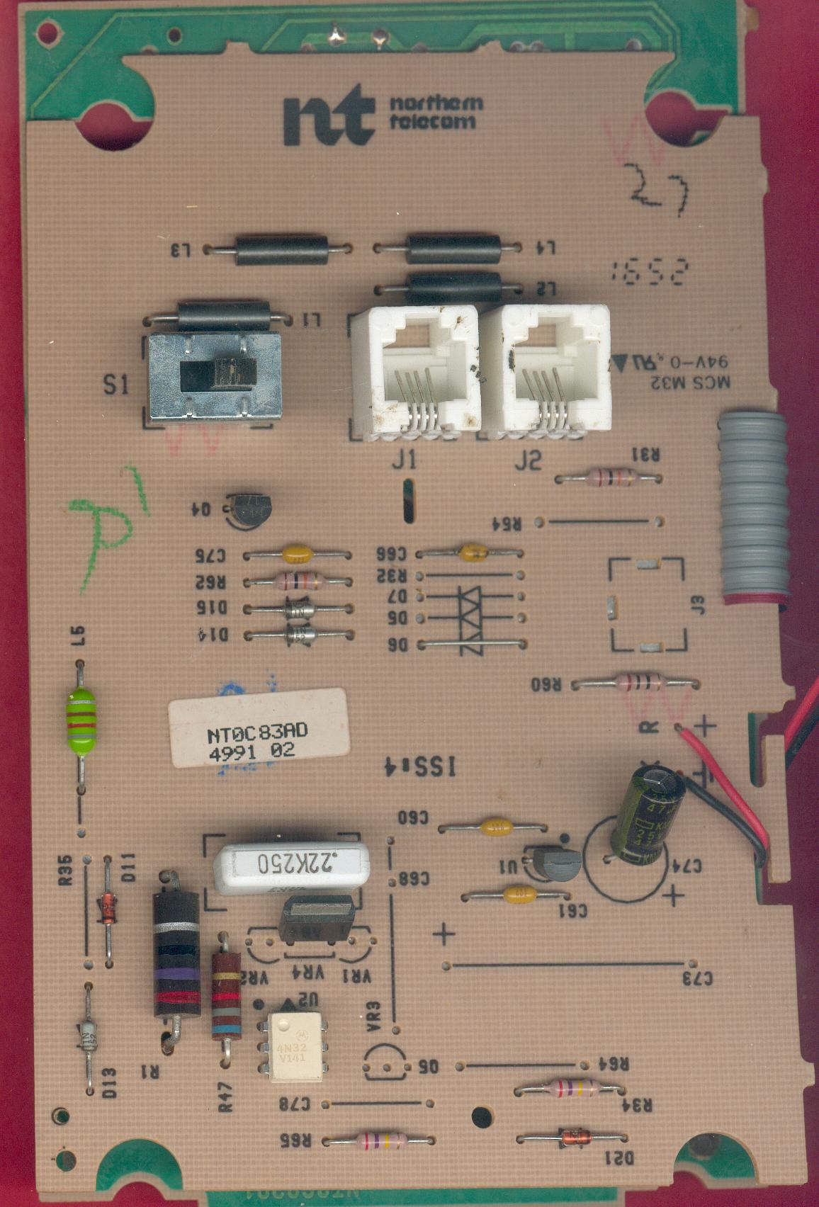
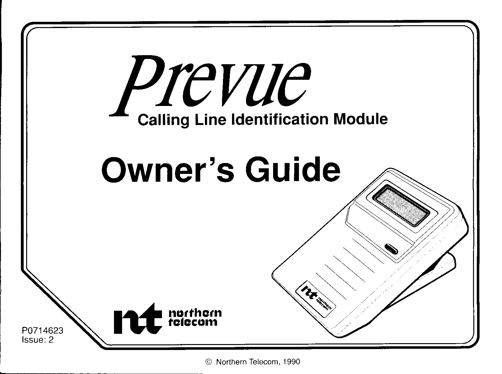
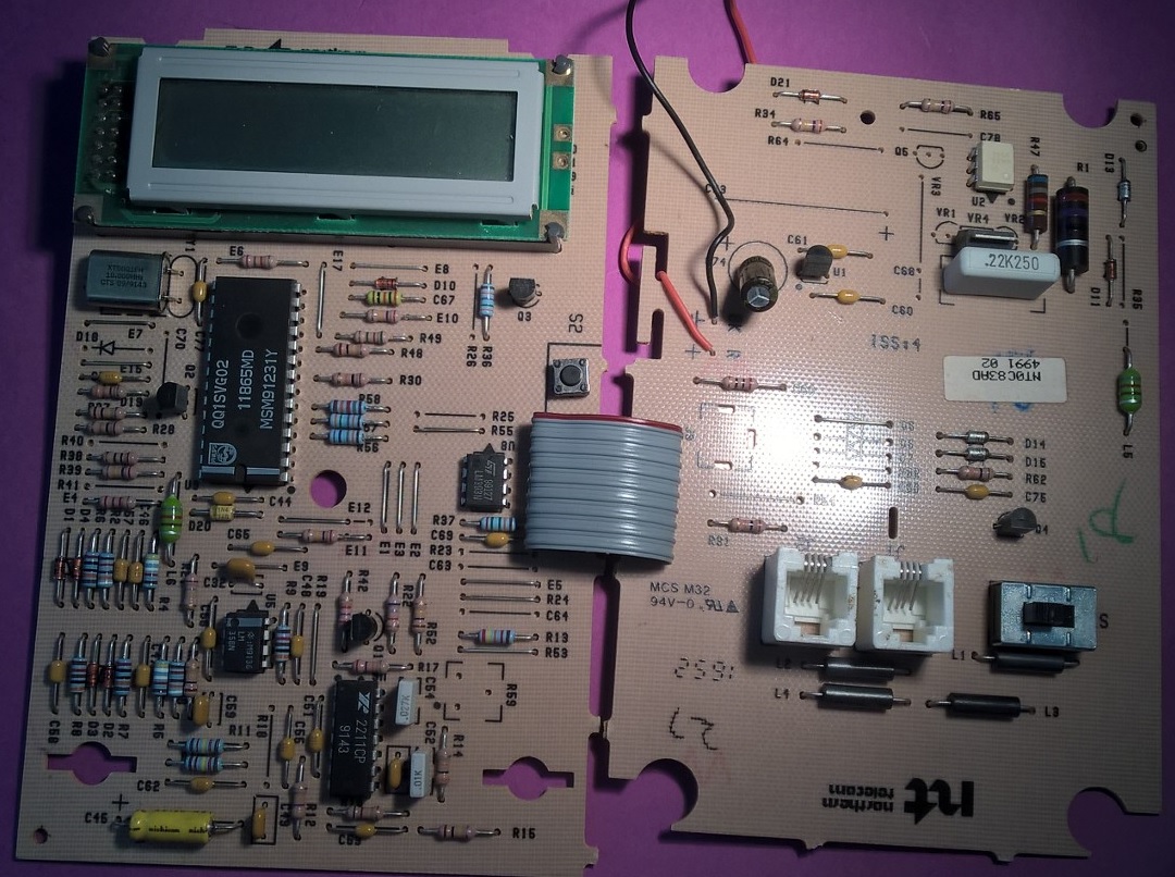
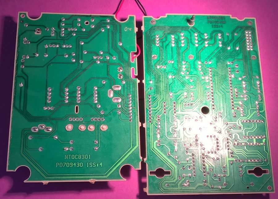
Northern Telecom Prevue caller Id unit based on Philips QQ1SVG02 11865MD MSM91231Y 28-pin microcontroller @10 MHz and the Exar XR2211
![]()
![]() cid_fr (PDF- 75Kb)
cid_fr (PDF- 75Kb)
![]()
![]() Circuits intégrés communication
(PDF- 2 pages - 22Kb)
Circuits intégrés communication
(PDF- 2 pages - 22Kb)
![]()
![]() Parafoudres (PDF- 3 pages - 261Kb)
Parafoudres (PDF- 3 pages - 261Kb)
![]()
![]() CPClare Surge Arresters (PDF- 7
pages - 1.32 Mb)
CPClare Surge Arresters (PDF- 7
pages - 1.32 Mb)
![]()
![]() Combiné Téléphone
(PDF- 4 pages - 832Kb)
Combiné Téléphone
(PDF- 4 pages - 832Kb)
![]()
![]() Système DTMF (PDF - 2 pages - 77Kb)
Système DTMF (PDF - 2 pages - 77Kb)
![]()
![]() Interface
Modem (PDF- 1 page - 720Kb)
Interface
Modem (PDF- 1 page - 720Kb)
![]()
![]() cartes Modems (PDF- 3 pages - 842Kb)
cartes Modems (PDF- 3 pages - 842Kb)
![]()
![]() IC DTMF+CallerID (PDF- 1 page - 71Kb)
IC DTMF+CallerID (PDF- 1 page - 71Kb)
![]()
![]() 13 mars, 2026
13 mars, 2026
Email :  matthieu.benoit@free.fr